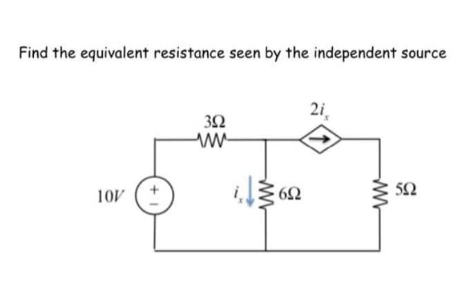
Find the equivalent resistance seen by the independent source 2i, 3Ω 52 10V


Q: For the circuit shown, the following mesh currents are given: ia = 3.41 A in = 1.214 A ic 876 mA id…
A:
Q: c. Use KCL to determine the current i, izis for the circuit given in figure 3 12 mA 8 mA 9 mA Figure…
A: Find the current i1 i2 i3 in the circuit using the KCL.
Q: 3. A given circuits in the Figure 3 below has an equivalent resistance 32 122 403 342 20 be Figure 1…
A: In this question we will find equivalent resistance.....
Q: 1KN O A 10V In 30ls 500n OB
A: Using Norton's theorom we can replace complex circuit with a current source and a resistor in…
Q: Find the drop voltage across R=20 ohm 10 N 2 30 N 10 A 1 20 N. V2 100 V
A:
Q: Calculate the equivalent resistance of the following circuit: 12 v 10 www R1 10 R2 10 R3
A: Given circuit:
Q: fa refrigerator draws 2.2 A at 120 V, what is its resistance? Your answer 9 This is a required…
A: Here i have solved it using the ohms law.
Q: The ammeter in the circuit shown below is measuring the current through R3. How many mA would you…
A:
Q: 20 kſ) 3 kN 5 kN 100 V {80 kN 12 mA {60 kM i310 k 10 kN 1 kN Figure 1
A:
Q: Analytically (show all necessary work) determine the Thévenin equivalent circuit seen by the 2.2 kN…
A:
Q: Find the drop voltage across R=20 ohm 10 N 2 30 N 10 A 20 N V2 100 V
A:
Q: 2. For the circuit shown, find the (a) total resistance (b) total current (c) current through each…
A: We will find out equivalent resistance then we will find out total current then voltage across each…
Q: Compute current, io(t) when vs(t) = 45 cos (100t + 35°) V as shown in Figure 3. ww io Vs 10 0 1 H 15…
A:
Q: Question 3 a). Taking Ci and C2 to be 6µF, 16MF 3V E L buF Find the Charge (a)
A:
Q: Solve for the total current by determining the equivalent resistance. Let Vs = 90, R = 39. %3D %3D…
A:
Q: A light bulb is rated for 60 W, 240 V. Find the resistance of the bulb. Ο 960 Ω Ο 1000 Ω O 8600 O4Q
A: Given: Power rating of bulb, P = 60 W Voltage, V = 240 V
Q: Find 1 in the circuit shown. 2 ΚΩ 2 k2 12 mA 10 k2 2 kN 2 k2 Select one: a. 12 mA Ob.3 mA C. 4 mA d.…
A: In this question we will find unknown current I 1..
Q: QI) Find the voltage V, for the circuit of Figure 1: R1 100 N R2 R4 300 N 50 N R3 200 N E 40 V
A: By ohms law current I=Voltage Resistance. Apply KVL in loop to get Vab. According to KVL sum of…
Q: Determine the voltage across the terminal A and B in volts. А 2.0 в 1.5 с 10 D 0.5 A B Find in ohms…
A:
Q: 20 1 600 180 80 mA( 601. $75 n 120 40 A 20 300 (b)
A:
Q: 1. Find the current in the circuit. 20 ohm 40 ohm 120V a) 1 A b) 2 A с) 3 А d) 4 A
A: According to the question we have to find the value of the current flowing in the circuit.
Q: A copper wire is having a resistance of 10Q at 20C° and 10.40 at 30C°. Then it's temperature…
A:
Q: For the shown figure below, if the voltage for resistance 32 is equal to 6V then -13 Is 12 n V 38n…
A: Nodal Analysis - It is used to find node voltage using Kirchhoff's current law. Kirchhoff's current…
Q: 1. Find the current flowing in the 10-ohm resistor. 102 35 62 20 V
A:
Q: R1 R2 R3 20 A 2 A 0,2 A
A: We need to find resistance value for given current .
Q: 3. For each of the circuit in figure 2, compute the voltage labeled ve 100 10n 130 3 mF 4.5 nA 13 sa…
A:
Q: A 9-volt battery with a 500 mAh capacity is connected to a circuit which draws 100 mA. How long will…
A: In this question given battery capacity is given and current drawn by circuit is also given...We…
Q: 1. Find the equivalent resistance between terminals A and B. 20 150 ww 10n2 3200 10n 300 400
A:
Q: Using a voltmeter measured value is 24.3V, while its true value is 24V. What is the relative error…
A: Given, Measured Value=24.3 V, True Value=24 V. %Relative error=Am-ATAT*100
Q: If the resistance in a circuit is given by 80 n± 0.2% and the current flowing through it is 5A ±…
A: The solution can be achieved as follows.
Q: What is the current through the 10-ohm resistance (R,) 1, E, 48V R, I, R2 10 2 20 2
A:
Q: .Use KCL and determine the currents i, iziz in the circuit in Figure 1 17 mA
A: The solution can be achieved as follows.
Q: For the circuit shown, find the (a) total resistance (b) total current (c) current through each…
A: In this question we will find total resistance , current , voltage drop across all resistance..
Q: For the circuit shown below, find the equivalent resistance (in ohms) across the voltage source Vs.…
A: As per our guidelines we are supposed to be answer the first question only. Kindly repost the other…
Q: Obtain the equivalent resistance for the circuit and use it to find current į. 12.5 Q 10Ω 5Ω 120 V…
A:
Q: Calculate the value of Rx if equivalent resistor at terminal a-b, Reg = 7.50 for the circuit…
A:
Q: In the circuits shown below, what is the value of current 14? 7Ω 2 0 2 0 E 24 V 4Ω 24 N 10 N 12 N 12…
A: We will use mesh Current analysis method Mesh Current Analysis is a technique used to find the…
Q: Calculate the thevenin equivalent resistance for the following circuit (across points A and B). R,…
A: Given, R1=150 ΩR2=100 Ω
Q: Consider the circuit below and answer questions 17 an4 n 0.54 50 30 R1 R2 0.4A 10V 7. Find the value…
A: The solution for the given is, V=10 V The current I is divided in the parallel connection as,…
Q: For the circuit of the Figure shown, find the following quantities: a. The current, I. b. The…
A:
Q: In a circuit, the potential drop across the 10 kQ -resistor is 100 V. What is the current through…
A: In this we will find current through resistor..
Q: Compute current, io(t) when vs(t) = 45 cos (100t + 35°) V as shown in Figure 3. ww io Vs : 10 Ω 1 H…
A:
Q: he circuit shown. The terminal voltage of the 24.0-V battery is 21.2 Volts. The external resistance…
A: In this question we will find external resistance with given value of terminal voltage of battery...
Q: H.W. a- calculate the equivalent resistance of the circuit below figure. 82 10 N 24 2 b. 18 Ω a b-…
A: The solution can be achieved as follows.
Q: Find the value of R so that Maximum power can be transferred to it by the sources. li 3i O10 A 312 b
A: To transfer the maximum power to 'R', it should be equal to the Thevenin equivalent resistance…
Q: QI/ Find the equivalent Resistance across(A, B). A o w
A:
Q: 4. Determine the voltage v, 2 A 15 N 4i-
A: To find the voltage vx
Q: Find Io in the circuit given below 4 kn 12 kn )9 mA 3 kn3 C6 kn
A: Transforming the given circuit according to convenience: ⇒
Q: Solve for the total current by determining the equivalent resistance. Let Vs = 81, R = 74. 12 2 10 N…
A: This question belongs to circuit theory . It is based on the concept of calculation of current by…


Trending now
This is a popular solution!

Step by step
Solved in 2 steps with 1 images

- Consider the circuit shown in the figure. Note that two currents are shown. Calculate the emfs ε1 and ε3.Use the thevenin equivalent resistance and Vth =?Explain the specific concepts and processes for the design methods that can effectively and efficiently design the electric and electrical systems (Ex. wireless power transfer systems, electric motors, solar power plants, etc.) in detail with some pictures and figures. MAKE A PRESENTATION WITH EXAMPLES.
- Using the diagram, solve for the Rth, Vth, and load current (IL) through each resistance using Thevenin’s Theorem. Please draw the circuit diagram for each Rth and Vth computation.Know how to design simple voltage-divider and currentdivider circuits Find the no-load value of vo in the circuit shown.Prove that VDS > VGS − VTH (saturation mode) in the circuit below. Show your complete solution.
- Draw the npn version of the circuit shown. Use the same circuit element values but change polarities as needed.Q23.For the circuit shown in the figure , find the operating point. What is the stability factor of the circuit ? Given that β = 50 and VBE = 0.7V.Explain the working principle of the circuit in details.
- a) Compare metallic foil vs semiconductor strain gauges (construction, advantages and disadvantages). b) Consider a Wheatstone bridge circuit (Figure 1) that has all resistances equal to 250 ?. The resistance R1 is a strain gauge that cannot sustain a power dissipation of more than 0.25 W. What is the maximum applied voltage that can be used for this bridge circuit? At this level of bridge excitation, what is the bridge sensitivity?For the JFET shown in Figure, Determine the minimum value of VDD required to put the device in the constant-current region of operation when VGS = 0 V. where VGS(off) = - 4 and IDSS = 42mAWith a neat diagram ,explain about the working of Dual Slope ADC.