Find the forces in parts AB, All, ED and EF in the Truss as shown in the figure and specify whether they are tensile or compressive forces.
Find the forces in parts AB, All, ED and EF in the Truss as shown in the figure and specify whether they are tensile or compressive forces.

Mechanics of Materials (MindTap Course List)
9th Edition
ISBN:9781337093347
Author:Barry J. Goodno, James M. Gere
Publisher:Barry J. Goodno, James M. Gere
Chapter5: Stresses In Beams (basic Topics)
Section: Chapter Questions
Problem 5.12.11P: A cylindrical brick chimney of height H weighs w = 825 lb/ft of height (see figure). The inner and...

Related questions
Question
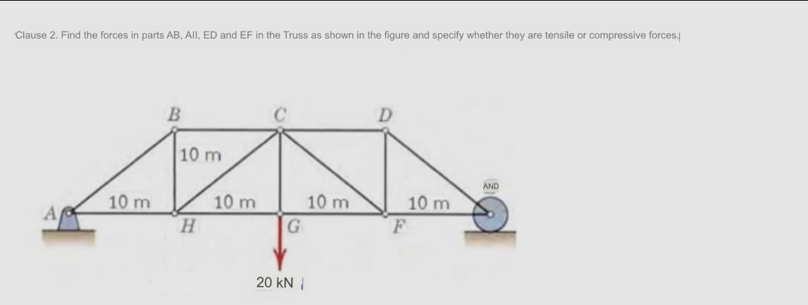
Transcribed Image Text:Clause 2. Find the forces in parts AB, All, ED and EF in the Truss as shown in the figure and specify whether they are tensile or compressive forces./
D.
10 m
AND
10 m
10 m
10 m
10 m
H.
A
20 kN |
Expert Solution
This question has been solved!
Explore an expertly crafted, step-by-step solution for a thorough understanding of key concepts.

Step by step
Solved in 2 steps with 3 images

Recommended textbooks for you
Mechanics of Materials (MindTap Course List)
Mechanical Engineering
ISBN:
9781337093347
Author:
Barry J. Goodno, James M. Gere
Publisher:
Cengage Learning
Mechanics of Materials (MindTap Course List)
Mechanical Engineering
ISBN:
9781337093347
Author:
Barry J. Goodno, James M. Gere
Publisher:
Cengage Learning