Find the power absorbed by the 10-Q resistor in the ideal transformer circuit given in the figure. Take Vs= 4620° V. 22 ww 1:2 V: 10 2 The power absorbed by the 10-Q resistor in the ideal transformer is W. ll
Find the power absorbed by the 10-Q resistor in the ideal transformer circuit given in the figure. Take Vs= 4620° V. 22 ww 1:2 V: 10 2 The power absorbed by the 10-Q resistor in the ideal transformer is W. ll

Power System Analysis and Design (MindTap Course List)
6th Edition
ISBN:9781305632134
Author:J. Duncan Glover, Thomas Overbye, Mulukutla S. Sarma
Publisher:J. Duncan Glover, Thomas Overbye, Mulukutla S. Sarma
Chapter3: Power Transformers
Section: Chapter Questions
Problem 3.28MCQ

Related questions
Question
need quick solution please
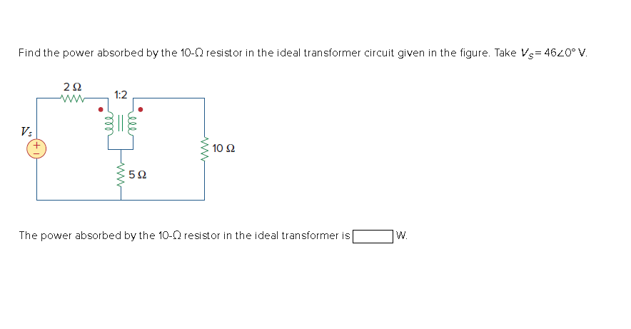
Transcribed Image Text:Find the power absorbed by the 10-0 resistor in the ideal transformer circuit given in the figure. Take Vs= 4620° V.
1:2
ww
V:
10 Ω
The power absorbed by the 10-Q resistor in the ideal transformer is
W.
Expert Solution
This question has been solved!
Explore an expertly crafted, step-by-step solution for a thorough understanding of key concepts.

This is a popular solution!

Trending now
This is a popular solution!

Step by step
Solved in 3 steps with 2 images

Knowledge Booster


Learn more about
Need a deep-dive on the concept behind this application? Look no further. Learn more about this topic, electrical-engineering and related others by exploring similar questions and additional content below.Recommended textbooks for you
Power System Analysis and Design (MindTap Course …
Electrical Engineering
ISBN:
9781305632134
Author:
J. Duncan Glover, Thomas Overbye, Mulukutla S. Sarma
Publisher:
Cengage Learning
Power System Analysis and Design (MindTap Course …
Electrical Engineering
ISBN:
9781305632134
Author:
J. Duncan Glover, Thomas Overbye, Mulukutla S. Sarma
Publisher:
Cengage Learning