Find the stFeady stete Sountio mpresponngg a,b 2 = Vs (t) %3D where Vs = lo0Cos2t + 25 Sin 2t + 2ou Cos4t +25Sin4t and R= S0 SL and C=0.04 F Steady state soh 9 A Sin 24 +B Cos Zt + C Sinut + D Go,4t Plot Vs vs t use ExceI, 9 vst
Find the stFeady stete Sountio mpresponngg a,b 2 = Vs (t) %3D where Vs = lo0Cos2t + 25 Sin 2t + 2ou Cos4t +25Sin4t and R= S0 SL and C=0.04 F Steady state soh 9 A Sin 24 +B Cos Zt + C Sinut + D Go,4t Plot Vs vs t use ExceI, 9 vst

Power System Analysis and Design (MindTap Course List)
6th Edition
ISBN:9781305632134
Author:J. Duncan Glover, Thomas Overbye, Mulukutla S. Sarma
Publisher:J. Duncan Glover, Thomas Overbye, Mulukutla S. Sarma
Chapter2: Fundamentals
Section: Chapter Questions
Problem 2.6P: (a) Transform v(t)=75cos(377t15) to phasor form. Comment on whether =377 appears in your answer. (b)...

Related questions
Question
K:21)
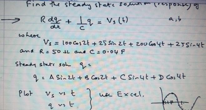
Transcribed Image Text:Find the steady state souti om respong
Po Gayad
Rdg + 19 = Vs (t)
a,b
where
Vs = loo Cos2t + 25 Sin 2t + 2ou Cos4t +25Sin4t
and R= S0SL and C=0.04 F
%3D
Steady state soh
9= A Sin 24 +B Cos Zt + c Sinut + D Cos4t
Vs vs t
1 vsヒ
P lot
use ExceI,
Expert Solution
Step 1
The equation are given as
Complementary function
So,
Step 2
Particular solution
So, complete solution
+
In steady state, exponential part become zero, so

Step by step
Solved in 4 steps with 2 images

Knowledge Booster


Learn more about
Need a deep-dive on the concept behind this application? Look no further. Learn more about this topic, electrical-engineering and related others by exploring similar questions and additional content below.Recommended textbooks for you
Power System Analysis and Design (MindTap Course …
Electrical Engineering
ISBN:
9781305632134
Author:
J. Duncan Glover, Thomas Overbye, Mulukutla S. Sarma
Publisher:
Cengage Learning
Power System Analysis and Design (MindTap Course …
Electrical Engineering
ISBN:
9781305632134
Author:
J. Duncan Glover, Thomas Overbye, Mulukutla S. Sarma
Publisher:
Cengage Learning