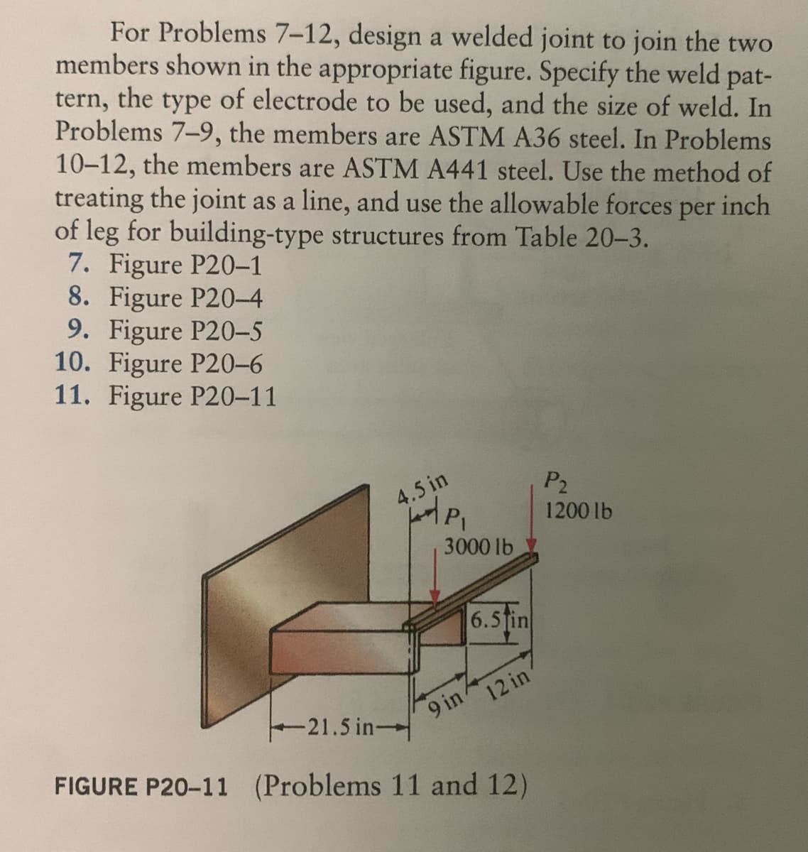
For Problems 7-12, design a welded joint to join the two members shown in the appropriate figure. Specify the weld pat- tern, the type of electrode to be used, and the size of weld. In Problems 7-9, the members are ASTM A36 steel. In Problems 10-12, the members are ASTM A441 steel. Use the method of treating the joint as a line, and use the allowable forces per inch of leg for building-type structures from Table 20-3. 7. Figure P20-1 8. Figure P20-4 9. Figure P20-5 10. Figure P20-6 11. Figure P20-11
For Problems 7-12, design a welded joint to join the two members shown in the appropriate figure. Specify the weld pat- tern, the type of electrode to be used, and the size of weld. In Problems 7-9, the members are ASTM A36 steel. In Problems 10-12, the members are ASTM A441 steel. Use the method of treating the joint as a line, and use the allowable forces per inch of leg for building-type structures from Table 20-3. 7. Figure P20-1 8. Figure P20-4 9. Figure P20-5 10. Figure P20-6 11. Figure P20-11

Welding: Principles and Applications (MindTap Course List)
8th Edition
ISBN:9781305494695
Author:Larry Jeffus
Publisher:Larry Jeffus
Chapter22: Welding Joint Design And Welding Symbols
Section: Chapter Questions
Problem 4R: Sketch a V-grooved butt joint, and label all of the joint's dimensions.

Related questions
Question
In the textbook (Machine Elements in Mechanical Design 6th Edition by Robert L. Mott, Edward M. Vavrek, and Jyhwen Wang) chapter 20 question 11. Im having trouble trying to understand and solve it with the information given to me. Image below.
Transcribed Image Text:For Problems 7-12, design a welded joint to join the two
members shown in the appropriate figure. Specify the weld pat-
tern, the type of electrode to be used, and the size of weld. In
Problems 7-9, the members are ASTM A36 steel. In Problems
10-12, the members are ASTM A441 steel. Use the method of
treating the joint as a line, and use the allowable forces per inch
of leg for building-type structures from Table 20-3.
7. Figure P20-1
8. Figure P20-4
9. Figure P20-5
10. Figure P20-6
11. Figure P20-11
4.5 in
P₁
3000 lb
6.5in
9 in 4
12 in
21.5 in-
FIGURE P20-11 (Problems 11 and 12)
P₂
1200 lb
Expert Solution
This question has been solved!
Explore an expertly crafted, step-by-step solution for a thorough understanding of key concepts.

This is a popular solution!

Trending now
This is a popular solution!

Step by step
Solved in 3 steps with 3 images

Knowledge Booster


Learn more about
Need a deep-dive on the concept behind this application? Look no further. Learn more about this topic, mechanical-engineering and related others by exploring similar questions and additional content below.Recommended textbooks for you
Welding: Principles and Applications (MindTap Cou…
Mechanical Engineering
ISBN:
9781305494695
Author:
Larry Jeffus
Publisher:
Cengage Learning
Welding: Principles and Applications (MindTap Cou…
Mechanical Engineering
ISBN:
9781305494695
Author:
Larry Jeffus
Publisher:
Cengage Learning