For R1=19, R2=28, R3=42, R4=69, R5=55, R6=19, R7=49, R8=57, R9=56 , R10=51 and 1=0.05 A in the circuit shown calculate the following: R1 R9 R2 R4 SR6 I1( R103 R8 ER3 R7 R5 a) the equivalent resistance seen by the source = b) the power developed by the source=
For R1=19, R2=28, R3=42, R4=69, R5=55, R6=19, R7=49, R8=57, R9=56 , R10=51 and 1=0.05 A in the circuit shown calculate the following: R1 R9 R2 R4 SR6 I1( R103 R8 ER3 R7 R5 a) the equivalent resistance seen by the source = b) the power developed by the source=

Delmar's Standard Textbook Of Electricity
7th Edition
ISBN:9781337900348
Author:Stephen L. Herman
Publisher:Stephen L. Herman
Chapter18: Resistive-inductive Parallel Circuits
Section: Chapter Questions
Problem 8PP: In an R-L parallel circuit, ET=48 volts, IT=0.25 amps, R=320. Find XL.

Related questions
Question
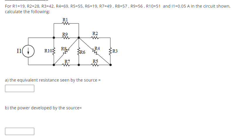
Transcribed Image Text:For R1=19, R2=28, R3=42, R4=69, R5=55, R6=19, R7=49, R8=57, R9=56 , R10=51 and 1=0.05 A in the circuit shown,
calculate the following:
R1
R9
R2
I1(
R10 R&
R4
R6
R3
R7
R5
a) the equivalent resistance seen by the source =
b) the power developed by the source=
Expert Solution
This question has been solved!
Explore an expertly crafted, step-by-step solution for a thorough understanding of key concepts.

This is a popular solution!

Trending now
This is a popular solution!

Step by step
Solved in 4 steps with 8 images

Knowledge Booster


Learn more about
Need a deep-dive on the concept behind this application? Look no further. Learn more about this topic, electrical-engineering and related others by exploring similar questions and additional content below.Recommended textbooks for you
Delmar's Standard Textbook Of Electricity
Electrical Engineering
ISBN:
9781337900348
Author:
Stephen L. Herman
Publisher:
Cengage Learning
Delmar's Standard Textbook Of Electricity
Electrical Engineering
ISBN:
9781337900348
Author:
Stephen L. Herman
Publisher:
Cengage Learning