For the beam and loading shown, (a) draw the shear and bending-moment diagrams, (b) determine the maximum absolute values of the shear and bending moment.
For the beam and loading shown, (a) draw the shear and bending-moment diagrams, (b) determine the maximum absolute values of the shear and bending moment.

Chapter5: Beams And Frames: Shear And Bending Moment
Section: Chapter Questions
Problem 53P: For the beam shown: (a) determine the distance a for which the maximum positive and negative bending...

Related questions
Question
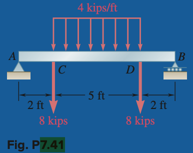
Transcribed Image Text:A
2 ft
с
8 kips
Fig. P7.41
4 kips/ft
- 5 ft -
D
2 ft
8 kips
B
Transcribed Image Text:For the beam and loading shown, (a) draw the shear
and bending-moment diagrams, (b) determine the maximum absolute
values of the shear and bending moment.
Expert Solution
This question has been solved!
Explore an expertly crafted, step-by-step solution for a thorough understanding of key concepts.

This is a popular solution!

Trending now
This is a popular solution!

Step by step
Solved in 5 steps with 6 images

Knowledge Booster


Learn more about
Need a deep-dive on the concept behind this application? Look no further. Learn more about this topic, civil-engineering and related others by exploring similar questions and additional content below.Recommended textbooks for you