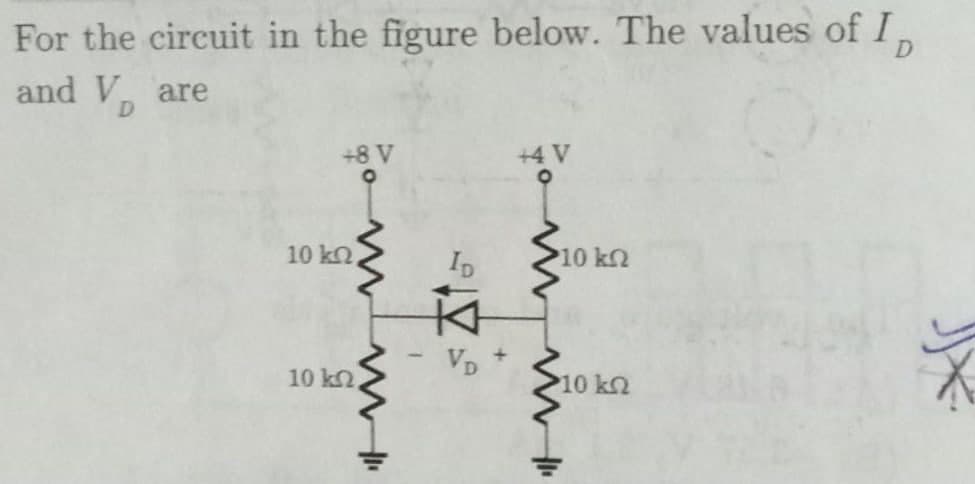
For the circuit in the figure below. The values of 1, D and V, are D +8 V +4 V 10 kn ID 10 kn Vo + 10 k2, 10 k2
Q: For this circuit Is and V2 = R1 R2 R3 2Ω + V2 Is Vs R4 12 V Select one: O a. Is = 2 A, V2= 2V O b.…
A: In this question we will find source current and voltage across 2 ohm..
Q: For the circuit shown in the Figure below, use superposition to find “v" in terms of R's and source…
A: According to the question we have to find the value of v.
Q: Hwt: Use the superposition theorem to find v in the Circuitin figure below. V. RI 852 R2 (t) 3A
A: Given circuit, According to superposition theorem told that a circuit with multiple current and…
Q: 5- Find v1 and v2 in the below circuit. 12 V 10 V
A: The solution can be achieved as follows.
Q: Q4: Find Rab for the circuit in figure below 20Ω ww- 16 2 ww ww 18 Ω 20Ω Rab 12 ww ww
A: To find the equivalent resistance
Q: 6Ω + 12 V 12 Ω V. 8 Η 4Ω t = 0 s
A:
Q: 50 2 0.04v2 100 2 10 V
A:
Q: For the circuit is shown in figure below, give the state space equations. 2H L 6F Ri R,5 30 Good…
A: Solution : Here we have to considerd the inductor current and capacitor voltage as a state…
Q: HW//1- For the circuit shown below, find the value V1 ,and V2. +30V- -50 V+ 40 V
A: 1) To determine the values of V1 and V2 in the given circuit
Q: For the following state table draw the simplest circuit using K-map. Present state Next state Next…
A:
Q: For the circuit in figure below, the value of R1 is: 2 A R1 R2 140 V O 44 0 15 0 О 100 O 23.8 Q
A: In this we will find resistance value of R1..
Q: For the circuit shown below: a +, 5i, O 3A R 452 32Ω 1- Find the maximum power that the circuit can…
A:
Q: Q3. For the circuit in the figure below, determine Va and le such that VB = Vc= BA/5, where BA is…
A: The given BJT circuit, Determine the value of VB and emitter current IE ? If VB = VC = 18/5 =…
Q: In the circuit diagram below, decreasing the value of V+ causes --- R1 R2 a decrease a slight an…
A: In this question we need to choose a correct option.
Q: For the circuit in figure below, the * :value of Vx is R3 120 R2 120 + vx - R1 V1 -12 V LV2 12 v R4…
A: Kirchhoff's Voltage Law (KVL): KVL: The total voltage drop across all the active and passive…
Q: In the circuit below, what is the value of the current 13? A 25 Ω F 0.52 A O 0.19 A O 0.71 A O 0.25…
A:
Q: 100 R1 100 R5 R4 2 K R7 1000 R8 200- 120 VAC R3 1 K 200 R2 R6 R6 = 100
A:
Q: Find the equivalent resistance of the circuit o a 4 A 4
A:
Q: Consider the circuit in Figure below; Find the equivalent resistance at terminals: (a) a-b, (b) c-d.…
A:
Q: What is the expression for thevenin's current if there is an external resistance R in series with R,…
A: Given: In a Thevenin's equivalent circuit, The Thevenin's resistance is Rth and external resistance…
Q: Discussion: Q: From based on your result, the total resistance in a series circuit is equal to the…
A: Resistance connected in series is given by,
Q: For the circuit shown, A) Ri is in series with R2 B) R4 is in parallel with R1 C) R2 is in parallel…
A: (A) is not correct because R1is not in series with R2 .( Since current through R1 and R2 are not…
Q: b. Simplify the circuit below such that there is only one current source Il and one equivalent…
A: we need to simplify the given circuit and RP.
Q: For the below circuit, perform a Delta==>Wye transformation and find R1 , R2 and R3 in Ohms. To…
A:
Q: For the circuit shown, the value of RL so that İL = 5 mA is equal to. 1.5 k2 15 k2 20 mA( 15 kN RL…
A: we will use source transformation to reduce the circuit into single voltage source and we will find…
Q: Consider the circuit in Figure below; Find the equivalent resistance at terminals: (a) a-b, (b) c-d.…
A: We will reduce the given circuit by series and parallel combination.
Q: By solving the circuit in the figure Find the Ix current, 10 current and the VO voltage. (Opamp is…
A:
Q: Q2 – For the circuit shown in the Figure below, use superposition to find “v" in terms of R's and…
A:
Q: For the circuit in figure below, the value of Vx is: * R3 120 R2 120 + vx R1 V1 V2 12 v R4 60 60 12…
A:
Q: HW//1- For the circuit shown below, find the value V1 ,and V2. + 30 V - - 50 V + + 20 V - + - 40 V
A:
Q: Determine and sketch v, for the network of the figure below for the input shown. Show the details of…
A:
Q: You need to design a voltage divider to drive a resistive load. One of the resistors has already…
A: Voltage Divider: Voltage divider is a passive linear circuit that results the division of input…
Q: Refer to the given circuit below. Determine the equivalent resistance across terminals a and b if R1…
A:
Q: Use mesh equations to find V in the circuits in Figure below. 6 V 4 kf 32 k! 2 kf? 6 kf 3 V ww
A: We will apply KVL in two loops , we will get mesh currents. Using ohms law we will find Voltage…
Q: For the below circuit, perform a Delta==>Wye transformation and find R1 , R2 and R3 in Ohms. To…
A: Find the value of resistance R1 R2 and R3 We are solving this problem using Delta to star
Q: With the following FET Calculate VD and VS by doing DC analysis of the circuit.? VGS (Th) = 4 V, k =…
A:
Q: Rf R2 R1 Vo V1 R3 If all resistances in this circuit are equal, the output is Select one: O a. V1xV2…
A:
Q: R2 R, R3 В R4 R5 C R1=12, R2=22, R3=32, R4=4Q, R5=62 What is the equivalent resistance for this…
A:
Q: For the circuit is shown in figure below, give the state space equations. 2H L Ri 6F R 30 8 Good…
A: Solution : The capacitor current is given by ic(t) ic(t) = C d/dt [Vc(t) ] Here capacitor…
Q: Arm resistances of Wheatstone bridge are, R = 200 N R, = 400 N R, = 500 Q R = 600 N Input is, E = 5…
A: Given: The circuit diagram would be:
Q: Q4/B)- Calculate the output voltages V 2 and V 3 in the circuit of figure below 250 ka 20 k2 V2…
A: For ideal opamp Voltage at inverting terminal is same as voltage at non inverting terminal, current…
Q: 4- In the circuit in following figure, obtain v1, v2, and v3. 15 V 25 V 10 V + '2 20 V
A: 4) The obtain V1, V2, V3 is as follows:
Q: the circuit shown below find vi and vz. 22 ww 12 A V2 10 Ω 5Ω 4Ω 6 A ww ww
A:
Q: 7) Find v2 for the circuit shown in Figure below + V2 50 N 0.04v2 100 Q. 10 V
A:
Q: For the circuit shown in the figure below B = 0, R = 10 k2, IVBEI = 0.7 v. Find V1. + 3.7 V Q2 V2 Qs…
A:
Q: Two resistors R, and R, are connected in parallel. If the resistance R, 20 & R 102 , find the…
A: When the changes in value are positive, the relative change and percentage change are also positive.…
Q: 6. Using at least one source conversion, solve for IRI for the given circuit. R3 20ka IR1 Is R1 R2…
A: Source transformation theorem :- If a voltage source is connected in series with a resistor then…
Q: Analyze the circuit shown in the figure and find out the value of R3 and R4. While R =1 kQ, R= 2 kQ,…
A: An OPAMP(operational amplifier) is an integrated electronic circuit that is used to amplify weak…
Q: For the circuit in the figure find R that will receive the maximum power transfer when…
A:
Q: Q5// For the circuit below, Find the node voltages v1and v2 12 A 102 50 40 O 6A ww + ww
A: 1) The given circuit consists of voltages and currents of each branch. Given the current I0=2A.…
Q: find io and vo in the circuit in the
A:
Q: For this circuit Is and V2 = R1 R2 20 R3 30 ww w m V2 - Is Vs R4 12 V 6Ω Select one: O a. Is 2 A,…
A: Let us find the required parameters using the concept of ohms law and also the series combination of…
Step by step
Solved in 2 steps
- In the circuit given below, R = 25 Ω. Find the current io.For the circuit in the figure find R that will receive the maximum power transfer when v(t)=100cos(1000t). Indicate the maximum power dissipated for the resistor.Compute for the following values and show complete solutions. 1.) Norton's Equivalent a.) isc b.) iN c.) VN D.) Draw circuit equivalent
- 1) Calculate complex power of L2 in the figure. R=10 ohm L1=0.015 H L2=0.037 H C=0.0008 farad ı sent you circuit's imageI NEED THIS SO QUICKLY HELP At the closed circuit ends in the figure, when v = 0, i = 1 A. When 20ohm resistor is connected to circuit endsThe voltage at its ends is 12 V. If a 12 V source is connected to the output of the circuit,Find the current drawn.In the circuit given below, R = 130 kΩ. Find the voltage v0. The value of v0 in the circuit is _______ V.
- for the circuit below, th value of k is dimensionless. for that cicruit, no solution is possible if the value of k is ___ the value of k so voltage is v is equal to 5.5VA circuit draws a current of (4 + j 3) A from a (150 - j 5) V source. What is the real power of the circuit?In the circuit , Calculate V0 if V1 = 0V and V2 = 0V
- 11. A series circuit has two resistors that dissipate 10 W and 15 W, respectively. What is the total power dissipation of the circuit? Select one: A. 15 W B. 10 W C. 5 W D. 25 WIn the circuit in Figure 1, Find the value v0 using Thevenin's Theorem.In the circuit given below, R = 70 Ω. Calculate v1 and v2. The value of v1 in the circuit is ______ V. The value of v2 in the circuit is _______ V.