For the circuit showni n figure if Vcc=20N RC=2:2K RB=390 KA , RE = 122 RC B-l00 Yo = 00 Finds 2) Ai 3) Av www
For the circuit showni n figure if Vcc=20N RC=2:2K RB=390 KA , RE = 122 RC B-l00 Yo = 00 Finds 2) Ai 3) Av www

Electricity for Refrigeration, Heating, and Air Conditioning (MindTap Course List)
10th Edition
ISBN:9781337399128
Author:Russell E. Smith
Publisher:Russell E. Smith
Chapter6: Reading Schematic Diagrams
Section: Chapter Questions
Problem 4RQ: Schematic diagrams break the wiring of control systems down into a(n) _____ arrangement. a....

Related questions
Question
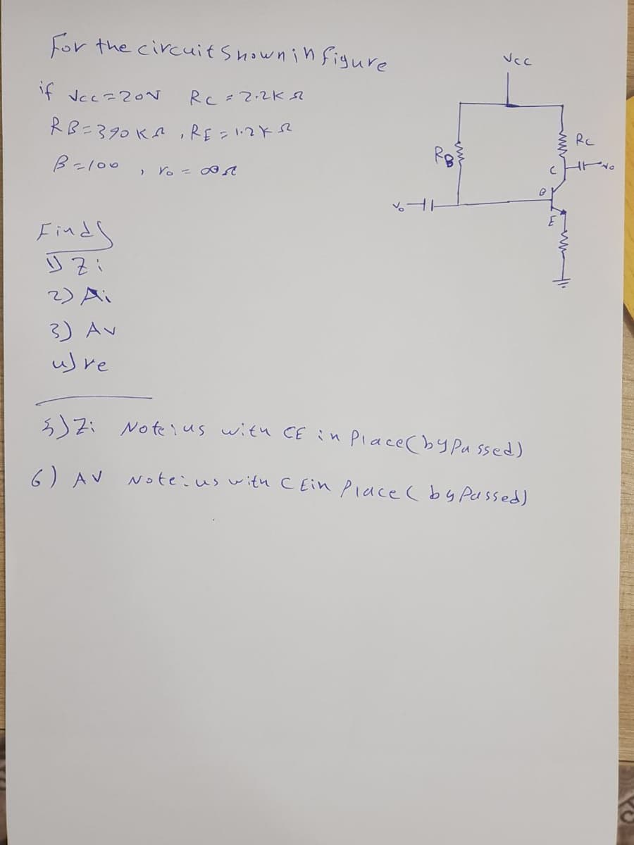
Transcribed Image Text:For the circuit shown i n figure
if Vcc=2ON
Rc=2.2K
RB=390 KA ,RE = 1:2KSR
RC
ビ。
B-l00
Yo = 0
Finds
2) Ai
3) Av
uJre
3)Zi Note ius with CEin Place(by Pa ssed)
6) AV
Note:us w itu CEin Piace (by Passed)
Expert Solution
This question has been solved!
Explore an expertly crafted, step-by-step solution for a thorough understanding of key concepts.

Step by step
Solved in 2 steps with 2 images

Knowledge Booster


Learn more about
Need a deep-dive on the concept behind this application? Look no further. Learn more about this topic, electrical-engineering and related others by exploring similar questions and additional content below.Recommended textbooks for you
Electricity for Refrigeration, Heating, and Air C…
Mechanical Engineering
ISBN:
9781337399128
Author:
Russell E. Smith
Publisher:
Cengage Learning
Electricity for Refrigeration, Heating, and Air C…
Mechanical Engineering
ISBN:
9781337399128
Author:
Russell E. Smith
Publisher:
Cengage Learning