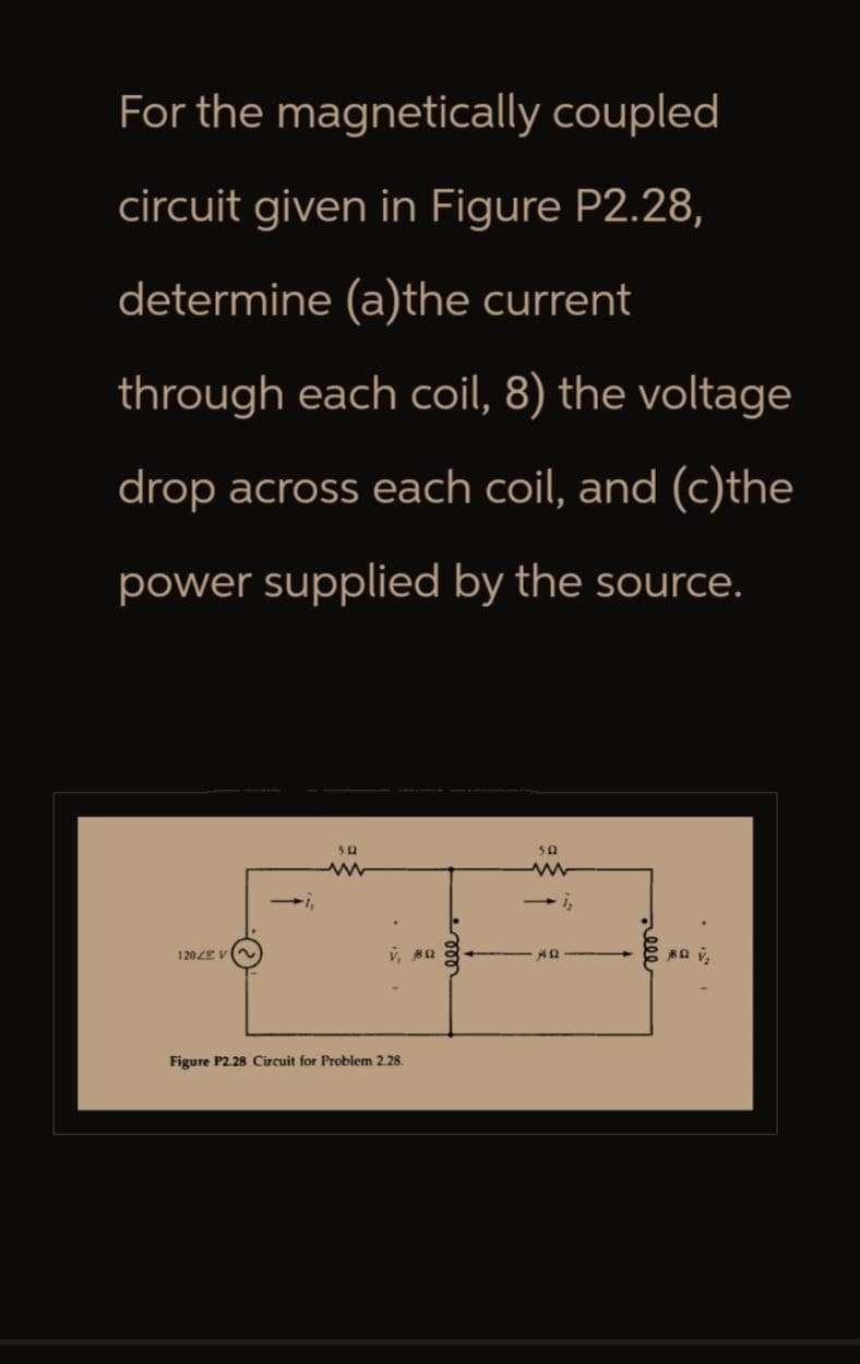
For the magnetically coupled circuit given in Figure P2.28, determine (a)the current through each coil, 8) the voltage drop across each coil, and (c)the power supplied by the source. 512 1202 V v, 80 Figure P2.28 Circuit for Problem 2.28. 000 50 www → 12 40 eee BQ V₂


Q: Compare the detection ranges of the two 3 cm radars above for a 10 ml target using a single pulse.…
A: According to the question, compare the detection ranges of the two 3 cm radars above for a 10 ml…
Q: I need the expert's solution in clear and complete handwriting.
A:
Q: The sketch below shows the Bode Magnitude plot for a system. 1- Obtain the open loop transfer…
A:
Q: The step-up converter in the next figure has R = 7.5 N, L = 6.5 mH, E = 5 V, and k = 0.5. Find I₁,…
A:
Q: Q4. For the circuit below, a resistive load of R = 102 and the input voltage is 220V. The voltage…
A:
Q: Thank you in advance!
A: Step 1:Step 2:Step 3:
Q: Table 4.1 shows the experimentally measured frequency response of an open-loop process plant G(s).…
A: Given:open loop transfer function of a control system, we need to do:a) Bode plot of given transfer…
Q: A circuit composed with series combination of sinusoidal voltage source V = 3 cos (100t - 3°)V, a Vs…
A: Impedance of Inductor (XL):The inductive reactance (XL) is given by XL=2∗pi∗f∗L, where f is the…
Q: None
A: Method 1: Pure circuit analysis Method 2: Conceptual analysis
Q: Q1: A discrete system described by the following difference equation - y(n) = x(n) 0.9x(n-1) -…
A: Here's the plot for part b: Here's the plot for part c:
Q: © Find (10) Point sequence yen, that DFT Y(K) = X(K) W(K) where X(K) is The (10) was Point PFT of…
A:
Q: This is a practice question from the Signal and Systems course of my Electrical Engineering Program.…
A: Step 1: Step 2:
Q: What is the value of C1 and frequency is 50Hz please answer in typing format
A: Frequency (f): The frequency of the circuit is 50 Hz, which means it oscillates 50 times per second.…
Q: Consider the circuit attached. If v = 130 V, how is the node-voltage method applied to find vo =…
A:
Q: None
A:
Q: A. Pz P MM- www P3 -mu- AMB Py m In the electrical circuit shown above, the values p1 =0.915,…
A: To find the probability that the circuit operates between points A and B, we can use the…
Q: "The topic is electromagnetic fields. I need an expert solution in written form."
A:
Q: What results when you open the circuit and stop current to an inductor? Select one: counter voltage…
A: The question is asking about the behavior of an inductor when the circuit it is part of is opened,…
Q: حوال .B. Write, if the shown statements are true or false, (Hint: you will lose points for each…
A:
Q: Determine the impedance of an inductor that has the value provided at the given frequency at 100 mH…
A: To determine the impedance (Z) of an inductor at a given frequency, we can use the formula for…
Q: Determine the Vo of the following inverting OpAmp:
A:
Q: Based on the following circuit, draw it again with the voltmeter andammeter connected to show how to…
A: Step 1: Step 2: Step 3: Step 4:
Q: Draw the circuit symbol and give the truth table for a positive-edge-triggered D flip-flop.
A: Step 1: Step 2: Step 3: Step 4:
Q: 16. Find D and plot D, vs. r for cách of the following charge distributions: (a) 1C at the origin;…
A: We need to find out electric flux density for given charge distribution .
Q: Please answer in typing format
A:
Q: Find the Thevenin and Norton equivalent circuits at terminals a-b for the circuit given below, where…
A:
Q: In a motor, increasing the gap between electromagnets and a rotor: Select one: decreases motor…
A: The question is asking about the effect of increasing the gap between the electromagnets and the…
Q: Please answer in typing format
A: Given, Vin = 4.4V, Ic = 5mA, hfe = 93 In the given circuit, Applying Kvl in 1, we get; -Vin + IBRB…
Q: Needs Complete solution with 100 % accuracy. Don't use chat gpt or ai i definitely upvote you. Be…
A: The objective of the question is to determine the type of binary sequence (overlapping or…
Q: 5. For the amplifier circuit below, i. Find the values for Rs and RD such that ID = 2mA and VD = 5V.…
A:
Q: Determine the Fourier series of the sawtooth waveform in Fig. 17.9. FLO) 4 -2 -1 0 1 2 31
A: From the sawtooth wave form, we have to determine the fourier series,Fourier series representation…
Q: ε.2 For the circuit shown, a) Find VA using The method of hode voltages. 32 W 22 5л 5V
A: Kindly see attached photo for your guidance.
Q: A two-stage inverter is shown in this figure. Vs=50 V. v=110V2 sin 100 nt. The average voltage of C…
A:
Q: Tranfrom the
A: Step 1:Step 2: Step 3: Step 4:
Q: Need Help with this homewok
A: 1. Gather Information:Column dimensions: You'll need the width (b) and depth (h) of the column…
Q: 10) The impulse response of the channel modeled as an LTI system is given as h(t) = 55(t-10). a)…
A: since you have posted a question with multiple sub parts, we will provide the solution only to the…
Q: The field strength of an electromagnet: Select one: remains constant as voltage across the coil…
A: The field strength of an electromagnet is a measure of how strong the magnetic field produced by the…
Q: Q3: A. By power series, prove that: d cosx == sinx dx
A: Step 1:
Q: Q1. Test the convergence and divergence of the following: 1. n=0 3 00 2. Con (-2) 3.2-17 115 2n2-11…
A: Approach to solving the question: Detailed explanation: Examples: Key references:
Q: 202 www If the input voltage in the circuit of Fig. 17.24 is 7 Vilt) 1 v(t)= + Cos nt - sin nt) V…
A: Step 1:
Q: This is a practice question from the Signal and Systems course of my Electrical Engineering Program.…
A: (a) (X1(ejω)=e−jω∑l=111sin(klω))This transform represents a complex signal because it contains…
Q: searching for the topic of production lines and the switches in them and PLC in production lines +…
A: Step 1: Step 3: Step 4:
Q: Please answer in typing format
A: The Voltage E: To find the voltage E for the equivalent voltage source, we use Ohm's…
Q: please dont use AI, it gives wrong answer thank u. solve by hand and i will like
A: Question i. a. If the ARM processor is configured as little-endian, it means that the least…
Q: I need help on this question, As for measure resistor value, Rmeasure = 991ohms
A: Step 1:
Q: As a capacitor charges, the current through it: rises according to the time constant. lags behind…
A: The question is asking about the behavior of the current through a capacitor as it charges. This…
Q: I connected the Wheatstone junction as shown in the figure below R1=100 Ω R2=1000 Ω R4=8962 Ω With…
A: 1)On balanced wheatstone bridge,R2R1=R4R3R3=R2R1∗R4R3=1000100∗8962R3 = 896.2 Ω 2)
Q: d) Explain how/why Y3 (k) resembles a delta impulse in frequency domain (what does the periodic…
A: Given:To do:d) How/why Y3(k) resembles a delta impulse in frequency domain?e) Sketch Y3(k) points on…
Q: Please answer in typing format
A: Finally, we combine the two terms using an OR gate:+-----+ a' -----+ +-----+ | |…
Q: Please answer in typing format
A: Step 1: Perform KmapF(a,b,c,d)1,2,3,5,9,12,14,15 = 0001, 0010, 0011, 0101, 1001, 1100, 1110,…

Step by step
Solved in 2 steps with 3 images

- A 500-turn coil is wound on an iron core. When a 120-V-rms 60-Hz voltage is applied to the coil, the current is 1 A rms. Neglect the resistance of the coil. Determine the reluctance of the core. Given that the cross-sectional area of the core is 5 cm2 and the length is 20 cm, determine the relative permeability of the core material.What do you understand by Ferranti effect? Subject Power Transmission and DistributionA circuit powered by a 20V DC supply has a 50kΩ resistor and 20 μ Capacitor connected in series. For this circuit determine the:a. Initial value of the current flowing? b. The time constant of the circuit? c. The value of current after 1 second of connection? d. The value of capacitor voltage 2 seconds after the connection?
- Write the application of super tension that have rating upto 33KV and what used for?Please answer the following points in detail and rigorously. Instead ofresort to formulas, develop from basic principles (laws ofvoltages and currents, definition of electrical power, properties ofphasors, among others) d) Show that the complex power consumed by two elements in parallel is the sum of the individual complex powers. After, repeat the procedure but for two elements in series. e) What meaning would you give to the P consumed by an element? Which to Q? f) Suppose you know P and Q for a two-terminal element. What is the power factor of this element? When would i be in early and when behind? g) Suppose you know the equivalent resistance R and the reactance X equivalent of a two-terminal passive network. What is the factor power of red bliss? When would I be in advance and when in backwardness?Q-1: Give brief answer to the following: (Answer Ten only)1) what is the potential transformer used for in power substation?2) what is process leads to lowering the number of free electrons?3) what is The Townsend’s Criterion4) why Sulphur Hexafluorid has good insulation strength?5) What is Intrinsic Breakdown6) why do bubbles lead to breakdown of liquid?7) how to decease the ripple voltage of cockroft-walton voltage multiplier circuit8) how much the maximum charging current of A Van de Graaff generator has a beltwidth 1 m, a belt speed of 4 m/s, and charge density of 10 c/m29) Why does need for Reactive Power Compensation in test transformer?10) The output voltage of series resonant circuit is given by the formula _________11) what is impulse voltage and what is its standard wave shape?12) Which advice can measure impulse voltage?
- In your own words, define a. an ideal conductor; b. an ideal voltage source; c. an ideal current source.Consider two interconnected voltage sources connected by a line of impedance Z=jX, as shown in Figure 2.27. (a) Obtain expressions for P12 and Q12. (b) Determine the maximum power transfer and the condition for it toConsider the interconnection shown 1. What value of α is required to make this a valid interconnection?2. For this value of α, find the power associated with the currentsource.3. Is the current source supplying or absorbing power?
- What is meant by FACTS in power systems? Discuss about UPFC type FACTS device.Construct the circuit in Figure 1 in the Circuit JS simulator. Note that the voltage source is given in RMS. Within Circuit JS while defining the max voltage of the voltage source include “rms” after the number to tell Circuit JS that this is a rms value. Also note that there are additional parameters when instantiating a transformer in Circuit JS. Leave these at the default values. Additionally, transformers may have problems simulating in Circuit JS. Answer the following: 1. From the simulation results, determine the power dissipated in R2 and compare to the expected value from the previous section.2. Change the transformer ratio (“Ratio” as a fraction when you “Edit…” the transformer component) to the value calculated in the previous section to provide maximum power transfer in R2. Note: In Circuit JS, Transformer Ratio = Primary/Secondary.3. Rerun the simulation, calculate the power dissipated in R2 and compare to the expected value from the previous section.4. Change the…A) What is an emf of self-induction? a) when there is an induced emf in a circuit due to a change of current in the circuit itself b) when there is an induced emf in a circuit due to a change of current in an adjacent circuit (one within magnetic reach) B) Under what conditions of current flow is a self-induced ernf produced? a) whenever the circuit is energized b) whenever the circuit is de-energized c) whenever the amount of current flow in the circuit varies d) all of the above C) What is the direction of a self-induced emf in relation to any change in current? a) the same direction as the current flow that caused it b) the opposite direction as the current flow that caused it c) may be either "a" or "b" d) neither "a" nor "b" D). In an inductive circuit, does the inductance have any effect on the flow of a steady current? a) yes b) no