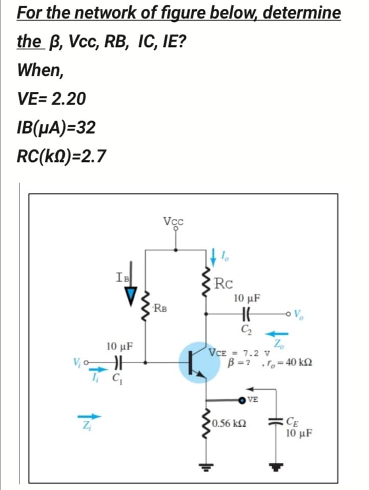
For the network of figure below, determine the B, Vcc, RB, IC, IE? When, VE= 2.20 IB(µA)=32 RC(kN)=2.7 Vcc IB Rc 10 μF RB C2 Zo VCE = 7.2 V B =? ,r,=40 k2 10 μF V, o VE =CE 10 μF 0.56 k2


Q: 2. Determine the value of currents la, la and le for the network shown in Figure below. 10 5V 10 V…
A: Given circuit,
Q: 2. For the network shown, determine the following a.) IR IT IR IL| b.) IL XL 60 ohms R c.) IT 25…
A:
Q: For the given network below, determine the current through the 1-kn 1 kN - j4 kN + 6 V. 10 VZ 0° 2…
A:
Q: For the network shown in figure below, determine:r., Zin, Zo, and A, ? Take: B = 100, RL = 0 and V3g…
A:
Q: Q.5 For the following network, find the Norton's equivalent circuit for the portion external to the…
A: Norton's Theorem-A linear RLC network containing more than one independent or dependent voltage…
Q: Convert the given star network into Delta network and calculate the sum of all the resistances in…
A: The given star network is We will convert it to delta network R1=10×20+20×5+5×105=3505R1=70 Ω…
Q: 2)Find the nodal voltages for the circuit shown below. 140 250 100 30V 180 160
A: We’ll answer the first question since the exact one wasn’t specified. Please submit a new question…
Q: For the circuit shown below, calculate Norton's equivalent current In at the point's a-b. 12 2 122…
A: In this question we need to find a Norton equivalent current at the point a-b
Q: 35 is 1 20 3 4Ω 4 VA 320 N +. 20 V is { 80 N 3.125 v. 40 Ω ref 2.
A: Nodal Analysis - It is used to find node voltage using Kirchhoff's current law. Kirchhoff's current…
Q: c. For the network below, determine Zi, Zo, and Vo if Vi = 2 mV 12 V 3 k2 120 k2 68 k2 10 µF 0.01 uF…
A:
Q: Determine the Norton equivalent of the following circuit, ISC and RN . Calculate the load current…
A:
Q: Problem 2 For the circuit shown, use Nodal Analysis to determine the values of the voltages Va, Vp…
A: Given
Q: Q.3). Find the currents in each loop by MESH theorem if input voltage Vs has waveform as shown…
A:
Q: 1. For the circuit shown, find the current i. 2A 42 SA 20
A: Given circuit:
Q: 12 V Example 3 Given the information appearing in the network, determine: Ic (а) Iс RC RB (b) RC Vc…
A:
Q: If two identical 3A, 100 Norton's equivalent circuits are connected in parallel with like polarity,…
A:
Q: 2. Given the information of the network shown below: L = 0.153 H, C = 0.3183 mF, lz = 5 2 60°A, and…
A: Given that frequency of the circuit is 50Hz. The inductor and capacitor reactance is written as…
Q: Obtain the Thévenin equivalent of the given network. Calculate Load Current for RL = 0 ohm , 1 ohms…
A:
Q: Given that V = 24 Volts, Find E in the circuit below. R= 62 R, = 42 R=162 R, = 12 24 V R; =42 %3D40…
A: A resistive network with known resistance values is given. The voltage across one of the resistors…
Q: CO3 3. A DC two-wire distribution line, 500m long and fed at one end is as shown in below circuit.…
A: In this question , two wire dc distribution line is given....We have to find voltage at point F with…
Q: Part II. In the given circuit below, determine the current flowing through each resistors using; Es…
A: The solution is given below
Q: For the given cct, answer the followings Vo 2Ω 82 ЗА 12V +. 2vo RI=42 The Norton current IN in (A)…
A: Given : In the question first of all they want to know the value of Norton current through the…
Q: For the network given below, determine VCEicut om 9+16 V 12 ka Ve Beta = 120 9.1 kA 6-12 V A) 4 V…
A: In cutoff region transistor acts as open circuit and collector current is zero. Apply KVL in outer…
Q: 15) For the circuit shown below, which choice do you expect is the voltage VR? Si R=IK www + V R Viz…
A:
Q: voltageOut R1 R v 330.46mV 2 1 4 voltageln 802 80Ω 1V C1 1kHz O 2µF O 2µF 0 0°
A:
Q: The length of the link shown in Figure 5.8 is: (a) 1 km (b) 3 km (c) 5 km (d) 7 km Figure 5.8 Input…
A: The solution is given below
Q: For the circuit below, write the KCL equation for nodes a, b, c, d, e, and f; and all possible KVL…
A: According to KCL, the sum of current entering the node and the sum of current leaving the node is…
Q: Figure 324.52 Refer to Figure 324.52. Point L on the ladder diagram should be connected at…
A: Two relays and two ladder diagrams are given. We need to choose the correct options to represent the…
Q: 5. Find VDs. 20 V 2.2 kQ 910 kO loss = 10 mA V, =- 4V 110 k. 1.1 kO
A:
Q: Use NODAL analysis to find vab and io Note: Intelligent ground placement in this circuit could…
A: We need to find out current and voltage for given circuit
Q: a) Determine the pole location of the system below b) Discuss the stability of the system and…
A: In this question, A control system is given Determine the pole of the system? And check the given…
Q: • The number of loop currents required is 3. 10 Q 15Q 25 Q 200 50 • This time we will choose the…
A: According to the question we have to find the value of I1, I2, I3, I5ohm, I10ohm, I15ohm, I20ohm.
Q: 222 RL 6v 442 222 332 Figure 2 6. Determine the current at the load laB in the given circuit in…
A:
Q: SV. 3A Io V 2A (A 10n 12 V kload Fin d : Thevenin Voltage CUTH) Thevenin Resistan ce (RTH), value…
A:
Q: H. W5 1-Use Thévenin's theorem to determine the current through load resistor RL for the circuit R1…
A:
Q: 1. Using mesh currents indicated in the circuit, determine i, lz,lz and i, in the following circuit.…
A:
Q: 2. For the given network, determine (a) I (b) Ic (d) 6 (d) VCE 918 V 560 ΚΩ IB 13.9 ΚΩ -Vc=8V Ic +…
A:
Q: 3Ω 12Ω. 9Ω :18Ω 6Α 12Ω 12Ω. 12Ω 4Ω
A:
Q: Example 5.5 For the RL parallel circuit shown, E = 23040° V at 50 Hz, R = 115 Q and L = 0.366 H. E =…
A: Dear,as per company guidelines we can answer only 3 sub-parts at a time, kindly post other sub-parts…
Q: Determine the approximate value of VDs of Figure 55. VDD 21V 910kn 2.2ka Q1 V. Ioss= 10mA V. =- 3.5V…
A: The solution is given below the answer is option c
Q: For the given network: (a) Determine re and βre. (b) Find Zi and Zo. (c) Calculate Av and Ai.
A: The solution can be achieved as follows.
Q: Figure Ql shows a network with following parameters: RBI = 41 kOhm, RB2 = 2.8 kOhm, %3D Rc = 1.5…
A: In the given small signal AC model first of all we have to short circuit that all the capacitors.…
Q: ix 25 Ω Μ 20 Ω 4. Given i = 5A in the circuit shown above. Find ix 10 Ω 5Ω 40 Ω
A: Given circuit, i0=5 A
Q: 4. Determine RTH of the given circuit in figure 1. 5. In problem 4, define VTH. 22 오 RL 6V 440. 1.…
A:
Q: NETWORK LAWS Using superposition theorem, determine the contribution of current source IA to the…
A: To solve the above problem, one should know the superposition theorem. It states that in any linear…
Q: Q1): For the circuit shown. Fill in the following blanks with right answer? VEE 45 1.2K -9V (0, 97,…
A: As per our company guidelines we are supposed to answer only first 3 subpart kindly repost other…
Q: 20 KVA, 2 5o0/250V, 50 HZ, trans fo Q2: A has the following test results : 0.C. T (L.V.Side) 250V,…
A: Given data:
Q: 8) For the Circuit determine the Voltages. a) Va , Vp , Vc , Va b) Vab , Vcb , Vcd c) Vad . Vca 2 kN…
A: Both voltage sources '44 V' and '20 V' are connected in opposite direction to each other. Hence, the…
Q: Determine the mesh currents lA, IB, lc, and the voltage Vo in the circuit shown below. A 8 K3 4 kn3…
A:
Q: If an MLO has 4 aluminum conductors #3/0 (THWN) select a conduit for a "D" panel with three-phase,…
A: Given information: Type of conductors #3/0 THWN. Number of aluminium conductors in a conduit is 4.…

Step by step
Solved in 3 steps with 2 images

- A three-conductor belted cable 15 mi long is used as a three-phase underground line for a 69 kV 50-Hz system. The cable common test results show that Ca= 0.15 µF/mi and C= 0.3 µF/mi. can you tell me what the 1. The capacitance of each phase to neutral in μF is 2. The total charging current in (A) 3. Conductor to sheath capacitance in (µF/mi) 4. Conductor to conductor capacitance in (µF) 5. If the first common test was performed on this cable, Ca is (uF/mi)(a) What are the voltages at vC1 and vC2 in the circuitas shown = −1.6 V if IEE = 2.0 mA,RC = 350 , and VREF = −1.25 V? (b) RedesignIEE and RC in the current switch described in part(a) to operate at one-fifth of the power with the samevoltages.Compute for IN, RN and the current passing though the 25-ohm resistor using Norton’s Theorem.
- Vbatt=25 VC1=90 ?CC2=75 ?CC3=60 ?CR1=160 ΩR2=120 Ωt2=21.6 msect3=27 msecConsider the circuit shown below which shows a battery connected to some resistors and capacitors along with some switches which will be toggled opened or closed at different times. The components are listed above. The capacitances are in microFarads (?F), the resitances are in Ohms (Ω), and the times are in milliseconds (msec). A stopwatch is started at time t1=0 ms. At that time, switch S1 is closed and all other switches are open and the capacitor is allowed to charge up.(a). (i)What is the charge (in uC) on C1 at the time the stopwatch reads t2=21.6 ms?a)3690 b)1520 c)5710 d)2630 e)683 f)1750 (a).(ii)What is the current (in mA) through R1 at t2=21.6 ms?34.9 30.4 114 13.6 73.6 52.4 (b)(i)What is the voltage (in V) across R1 at t2=21.6 ms?8.37 5.58 2.18 11.8 18.2 4.85(ii). What is the voltage (in V) across C1 at t2=21.6 ms?63.2 29.1 40.9 7.57 19.4 16.9(c). (i) What is the energy (in mJ) in C1 at t2=21.6 ms?6.63…For the configuration shown in the figure below, determine Zi if Vs = 40 mV, Sense = 0.5 kΩ, and Ii = 20 µAA 3-ph, double circuit O.H.T.L, 420 kV, 350 km, 50 Hz has a configuration as shown in the figure below where each phase in the double circuit has a double bundle with a spacing of 24 cm between the two conductors in the bundle Each conductor in the bundle has a diameter of 0.115 ft and a geometric mean radius (Ds = 1.7 cm). Calculate: [10] 1- Inductance per phase per km and total inductive reactance of this T.L. 2- Capacitance per phase per km and total capacitive reactance of this T.L. 3- Total charging current. 4- Total MVAR generated by the capacitive effect. 5- This T.L. is required to supply 260MVA at 0.85 lag P.f. at 420 kV, assuming that this load is divided equally between these two circuits, find the voltage drop across this T.L (ignore capacitive effect in the calculation).
- Given: D1: GaAs, Rb = 2 ohms, Rr = 375 kilo-ohmsD2: GaAs, Rb = 3 ohms, Rr = 200 kilo-ohmsD3: GaAs, Rb = 5 ohms, Rr = 150 kilo-ohms Determine ID1, ID2, ID3 using 3rd approximation please do not answer if this question is posted for 25 mins nowA Victoria plaza sub-station supplies 60kW to a load over 250 ft, 100mm2 , two conductors copper feeder, the resistance of which is 0.078 ohm per 100 ft. The bus bar voltage is maintained constant at 600V.Determine the load currentLet a series RLC network be connected to a source voltage V, drawing a current I. (a) In terms of the load impedance Z=ZZ, find expressions for P and Q, from complex power considerations. (b) Express p(t) in terms of P and Q, by choosing i(t)=2Icost. (c) For the case of Z=R+jL+1/jC, interpret the result of part (b) in terms of P,QL, and Qc. In particular, if 2LC=1, when the inductive and capacitive reactances cancel, comment on what happens.
- A lossy capacitor Cx, rated for operation of 5 kV, 50 Hz is represented by an equivalent circuit with an ideal capacitor Cp in parallel with a resistor Rp. Cp is 0.102 microF and Rp=1.25 Mohm. The power loss, and loss tangent of this lossy capacitor at rated voltage respectively ?A RL network supplied with 10V battery (a)Find the mathematical expressions for the transient behaviour of vL, iL , vR2 and vR2 when the switched is moved to position 2. Sketch the curves of vL, iL and vR2.A how much time must pass before it can be assumed, for all practical purposes, that iL=0A and vL = 0 Volt?For the circuit shown, since IR5 is flowing out of the short circuit, the value of IR5=0 as current will travel the short circuit path instead. Am i right? Also, is IR4=0 as well