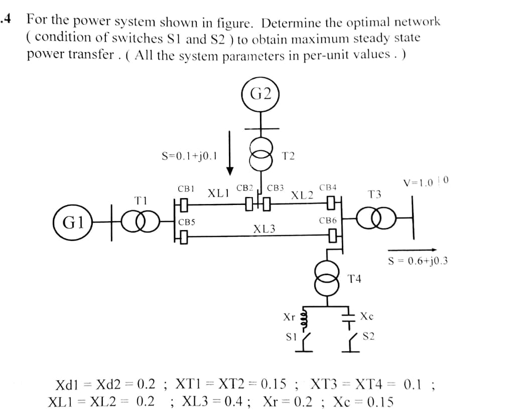
For the power system shown in figure. Determine the optimal network ( condition of switches S1 and S2 ) to obtain maximum steady state power transfer. (All the system parameters in per-unit values.)
Q: example open loop system
A: In this question we discuss about open loop system
Q: How can we determine the unit power cost?
A: A unit of the power cost is the amount on which electrical supply companies will supplied the…
Q: Discuss basic character of smart grid
A: Smart grid is one type of the electrical grid that is used efficiently and able to integrate the…
Q: Discuss the pressure response in figure l after using the PID controller in terms of the Rise Time,…
A: A PID controller's working premise is that each of the proportional, integral, and derivative terms…
Q: Application of load flow in power market?
A: There are various applications of load flow. Some of them are mentioned below, It is used to…
Q: 1.Thyristor-Switched Series Reactor (TSSR) for power factor improvement
A: NOTE: As per the policy, I can only answer one question at a time. Please ask the second question…
Q: Application of load flow analysis in power system planning in detail
A: Load flow study is considered to be one of the most important and detailed study of the power system…
Q: Q4: A power distribution station consisting of 100OKVA, 4500V/225V, and 50 cycles per second…
A: Write the expression for the number of turns,
Q: explain the operating principle of single phase 2S-2P PMSM based on 3D design illustration.
A: According to the question, explain the operating principle of single-phase 2S-2P PMSM based on 3D…
Q: r the circuit shown below, the
A:
Q: A 60-Hz synchronous generator having inertia constant H9.94 MJMVA and a transient reactance X0.3 per…
A:
Q: For the closed- loop system shown in the figure below. The steady-state error to a unit step is…
A: According to question: a) The value of 'K' for zero steady state error is calculated as…
Q: (b) Figure Q2 shows a power system network. The generators at Bus 1 and Bus 2 are represented by…
A: i) Admittance network of the given system
Q: For the switching converter shown in the following figure, assume steady- state operation. Also…
A:
Q: In the above figure, a single line model of a three-phase power system is given. Base power 50MVA,…
A:
Q: At the end of the 8 km overhead line given in the figure below, there are two distribution…
A: According to question: The currents 'I1' and 'I2' in the distribution transformer is calculated as
Q: Is desirable to have leading power factor loads? Why? Please explain.
A: The phase difference between current and voltage in an electrical circuit is defined by the power…
Q: 6. Explain following with examples and diagrams. a. Load curve b. Plant capacity factor c. Mean time…
A:
Q: What happens if a new pi equivalent circuit given the busbar admintas matrix and reactance and…
A: If a new element is added in two buses, then it will not affect the other bus matrix elements. As…
Q: Find the system Power Factor, please and thank you
A:
Q: In the transmission system shown in the figure above, the rated kVA of transformer 1, T1, is 1000…
A:
Q: Are sums of components powers equal to zero? Why
A: Yes The sum of components powers equal to zero
Q: The static load flow equations are..............equations.
A:
Q: Discuss with block diagram, the principle of operation of single phase energy met
A: (i provide you the solution in RULE PAPER for easily understand to the diagram and its related…
Q: Discuss FOUR (4) advantages of per-unit system.
A:
Q: 1. Why sub transient current magnitude is large compare to steady state current?
A: In power system transient and sub transient current it is occur only when three phase fault occur in…
Q: В2. Draw the block diagram of a close loop system. Also find the expression for steady state error…
A: the study state error constant for the unit ramp input is velocity error coefficient that is Kv
Q: he topic of the assignment is SMART GRIDS and it will be in form of power point presentations. Here…
A: Sorry as per Bartleby guidelines i can not provide you any PowerPoint power presentation but yes I…
Q: RIS)
A: Given system
Q: Explain all the additional components in Natural gas based Combined Cycle power plants which enhance…
A: The additional components in Natural gas based Combined Cycle power plants are - 1. Gas turbine -…
Q: For minimum cost of power generation the generator limits are consider as inequality constraints…
A: for the economic power generation the value of the power generation by the generator should be…
Q: Describe the ultimate cycle method, including the satisfactory perfor- mance. Also briefly discuss…
A: For system the maximum slope line starts at its origin , the delay is identified as the time at…
Q: Write the types of power factor improvement.
A: Power Factor: The ratio of real power to that of the apparent power is known as power factor.
Q: . Discuss in detail about the line commutated converters and voltage source converters for DC…
A: Line-commutated converters (LCCs) It is the standard technologies that is used to convert electrical…
Q: A) Highlight two significances of power factor correction.
A: We are authorized to answer one question at a time, since you have not mentioned which question you…
Q: Per unit (pu) is commonly used for the calculation of voltage, current, impedance and power in power…
A: per unit value(p.u): per unit(p.u.) value is defined as the actual value in any unit divided by the…
Q: The figure below shows the one-line diagram of a four- bus power system. The voltages, the scheduled…
A: Note: We are authorized to answer three subparts at a time since you have not mentioned which part…
Q: A generating system contains three 20 MW generating units each with a 3% FOR and one 45 MW unit with…
A: A table for unit system capacity outage is shown below:
Q: Discuss the reasons that make the load flow problem non-linear.
A: A series of nonlinear algebraic equations must be solved to address the load flow problem. Its…
Q: synchronous transients and stator phase resistance are neglected. then find the linearized equations…
A: In a synchronous machine, the torque, speed, and flow of mechanical and electrical powers are shown.…
Q: Explain the phase advancer method in power factor improvement?with a proper diagram.
A: According to the question we have to explain the phase advancer method in power factor improvement ?…
Q: in distribution transformers; What is 30 degrees phase shift in delta-star connection? What are the…
A: In the star-delta connection, the primary side of the transformer is in delta configuration while…
Q: 1. Thyristor-Switched Series Reactor (TSSR) for power factor improvement
A: Dear student as per our guidelines we are supposed to solve only one question.kindly repost other…
Q: 8- What do you understand from the load curve and what information are converged by a load curve.
A: The following are the information obtained from load curves. 1. Load duration curve determines the…
Q: 3. The fuel-cost functions in S/h for two 800 MW thermal plants are given by F = 400 + 6.0P, +…
A: Generator- A generator is a machine that generates electricity by converting mechanical energy into…
Q: a) Write the Biot-Savart Law for a steady current I.
A: “Since you have asked multiple question, we will solve the first question for you. If you want any…
Q: In the power system network shown in Figurebelowbus 1 is a slack bus with V = 1.020° per unit and…
A: Given the system is analyzed using the Gauss seidel method as shown below
Step by step
Solved in 4 steps with 10 images
- Consider two interconnected voltage sources connected by a line of impedance Z=jX, as shown in Figure 2.27. (a) Obtain expressions for P12 and Q12. (b) Determine the maximum power transfer and the condition for it toThe units of admittance, conductance, and susceptance are siemens. (a) True (b) FalseI have just started my first Semester (Fall 2021) out of 4 semesters in Master of Applied Science (M.A.S) in Power Engineering at Illinois Institute of Technology. I did not clearly undersand the course enrollment system because I am new to the system, so I ended up enrolling in courses; ECE58-Microgrid Design and Operation, and ECE579-Computer Aided Design of Electrical Machines. It appears ECE582 listed ECE418 (Power System Analysis) as a prerequisite; and ECE539 requires ECE319 (Fundamentals of Power Engineering) and ECE412(Hybrid Electric Vehicle Drives) as prerequisites. Let me hasten to add that I graduated in 2009 in a different academic setup in Africa in Electrical Engineering. So, not only do I have to cover the gap of about 12 year out of classroom, but I have compounded the problem by jumping into advanced courses before enrolling into foundation courses. Unfortunately I can no longer switch courses as the enrollment window has passed. I am only left with one option; to…
- A power system has 2 buses with bus1 as slack bus and bus 2 as PQ bus and bus voltages as V1=20 and V2=20. The admittances are Y11=Y22=492, Y12=Y21=181. Find the real and reactive power in the slack bus. Real Power = Reactive Power =Derive conditions for economics dispatch when generating stations are connected in parallelS1) The serial impedance per unit length of a three-phase 140 km power transmission line is 0.09 + j0.88 ohm/ km and its admittance is j4.1x10-6 S / km. Power factor under 210 kV interphase voltage from the end of this energy transmission line A power of 150 MVA, which is 0.85 back, is drawn. Using this transmission line data and the T equivalent circuit model, the line Calculate the head voltage (V1), current (I1) and load angle.
- Complete the table using Kirchhoff's Laws Compose the voltage equations based on the variables given.Retain the signs generated by the tracing directions. Multiply with the least common factor to remove any fractions. KVL @ loop A: k11Vx + Z12Ix + Z13Iy = Source1 KVL @ loop B: k21Vx + Z22Ix + Z23Iy = Source2 KVL @ loop C: k31Vx + Z32Ix + Z33Iy = Source3Discuss the role of FACTS (Flexible Alternating Current Transmission Systems) devices in power system control and optimization.Power system planning can be done only after conducting a. Power flow analysis b. Economi dispatch c. Generation flow analysis d. Unit commitment
- A gantry crane of weight W=100 Kg moves across a bridge with the length /=5 m. The front axle of the crane (which is nearer end A) carries 3/4W whereas the rear axle (nearer end B) carries 1/4 W. The distance of the axles is b = 1/20. Determine the maximum value of the bending moment and enter your answer in N-m units.. Remember to also show all your work (FBDs, calculation steps, etc on the handworked file) HINT: Determine the shear and bending moment equations along the beam. Assume only concentrated loads at the front and rear axles. So it’s wrong answer 1136 N can anyone how to solve for it different ?Consider a Pumped storage micro-hydel plant is to be built as a Peak load-plant on above mentioned Nathiya-Galli Water Fall with available head of 39 m and average discharge of 5640 m³/hour from the upper pound. The hydraulic efficiency and electrical efficiency of the plant to be 0.86 & 0.92 respectively. Analyze the following output from the above Pumped Storage Plant: a. Hydro-Power and Annual Hydro-energy available b. Electrical Power and annual electrical energy units that can be generated from the plant.3 A biomass plant with a power rating 137 MW has a power cost of $63 per MWh, while a plant with a power rating of 450 MW has a power cost of $50.30 per MWh. Determine the power sizing exponent, x.