For the shaft shown in the figure below, compute the angle of twist of pulleys B and C relative to A. The steel shaft has a diameter of 35 mm throughout its length. The torques are T1= 1500 N · m, T2 = 1000 N · m, = 500 N · m. The lengths are L, = 500 mm, L2 = 800 mm. T3 L2 T |T2 T3 A C B.
For the shaft shown in the figure below, compute the angle of twist of pulleys B and C relative to A. The steel shaft has a diameter of 35 mm throughout its length. The torques are T1= 1500 N · m, T2 = 1000 N · m, = 500 N · m. The lengths are L, = 500 mm, L2 = 800 mm. T3 L2 T |T2 T3 A C B.

Mechanics of Materials (MindTap Course List)
9th Edition
ISBN:9781337093347
Author:Barry J. Goodno, James M. Gere
Publisher:Barry J. Goodno, James M. Gere
Chapter3: Torsion
Section: Chapter Questions
Problem 3.12.3P: A full quarter-circular fillet is used at the shoulder of a stepped shaft having diameter D2= 1.0...

Related questions

Question
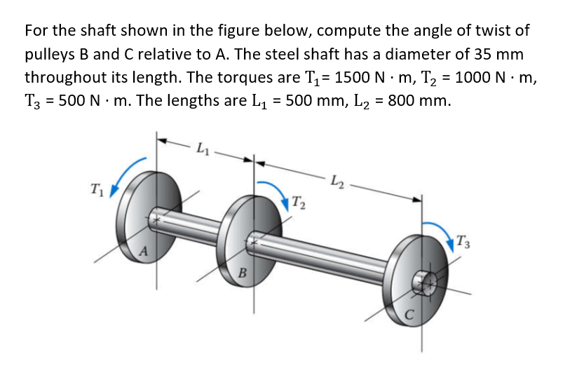
Transcribed Image Text:For the shaft shown in the figure below, compute the angle of twist of
pulleys B and C relative to A. The steel shaft has a diameter of 35 mm
throughout its length. The torques are T1= 1500 N · m, T2 = 1000 N · m,
= 500 N · m. The lengths are L, = 500 mm, L2 = 800 mm.
T3
L2
T
|T2
T3
A
C
B.
Expert Solution
This question has been solved!
Explore an expertly crafted, step-by-step solution for a thorough understanding of key concepts.

This is a popular solution!

Trending now
This is a popular solution!

Step by step
Solved in 2 steps with 2 images

Knowledge Booster


Learn more about
Need a deep-dive on the concept behind this application? Look no further. Learn more about this topic, mechanical-engineering and related others by exploring similar questions and additional content below.Recommended textbooks for you
Mechanics of Materials (MindTap Course List)
Mechanical Engineering
ISBN:
9781337093347
Author:
Barry J. Goodno, James M. Gere
Publisher:
Cengage Learning
Mechanics of Materials (MindTap Course List)
Mechanical Engineering
ISBN:
9781337093347
Author:
Barry J. Goodno, James M. Gere
Publisher:
Cengage Learning