From Figure 3, write node-voltage equations: one for each input terminal of the op amp. o. The expression for the load current (i,) can be written as a function of the input voltage (vm) and the load voltage (v,) i, = Av, + Bv, b.1. What is the expression for A? b.2. What should be the condition for R,, R, R, and R, so that B is zero? (NB: this condition will make i, depend only on v, and not on R.) R4 R3 OA1 R2 R1 Vin RL Figure 3
From Figure 3, write node-voltage equations: one for each input terminal of the op amp. o. The expression for the load current (i,) can be written as a function of the input voltage (vm) and the load voltage (v,) i, = Av, + Bv, b.1. What is the expression for A? b.2. What should be the condition for R,, R, R, and R, so that B is zero? (NB: this condition will make i, depend only on v, and not on R.) R4 R3 OA1 R2 R1 Vin RL Figure 3

Delmar's Standard Textbook Of Electricity
7th Edition
ISBN:9781337900348
Author:Stephen L. Herman
Publisher:Stephen L. Herman
Chapter18: Resistive-inductive Parallel Circuits
Section: Chapter Questions
Problem 13PP: In an R-L parallel circuit, IT=1.25 amps, R=1.2k, and XL=1k. Find IR

Related questions

Question
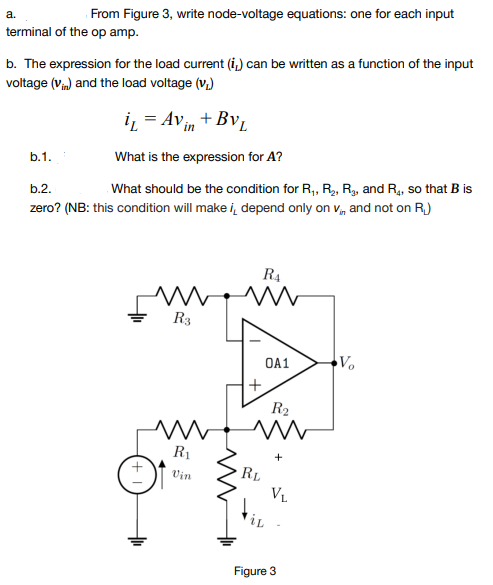
Transcribed Image Text:From Figure 3, write node-voltage equations: one for each input
a.
terminal of the op amp.
b. The expression for the load current (i.) can be written as a function of the input
voltage (V) and the load voltage (v.)
iz = Avin + Bv,
b.1.
What is the expression for A?
What should be the condition for R, R, R, and R4, so that B is
b.2.
zero? (NB: this condition will make i, depend only on v, and not on R.)
R4
R3
OA1
R2
R1
RL
Vin
VL
iL
Figure 3
Expert Solution
This question has been solved!
Explore an expertly crafted, step-by-step solution for a thorough understanding of key concepts.

Step by step
Solved in 3 steps with 3 images

Knowledge Booster


Learn more about
Need a deep-dive on the concept behind this application? Look no further. Learn more about this topic, electrical-engineering and related others by exploring similar questions and additional content below.Recommended textbooks for you
Delmar's Standard Textbook Of Electricity
Electrical Engineering
ISBN:
9781337900348
Author:
Stephen L. Herman
Publisher:
Cengage Learning
Delmar's Standard Textbook Of Electricity
Electrical Engineering
ISBN:
9781337900348
Author:
Stephen L. Herman
Publisher:
Cengage Learning