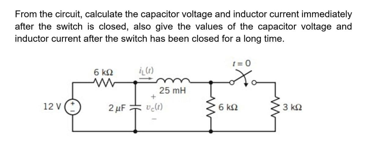
t = 0 6 k2 25 mH 12 v (* 2 µF velt) 6 k2 3 k2


Q: Nanoparticles exhibit unique properties due to their high surface area to volume ratio. Select one:…
A: Answer: True
Q: Q3/ when the bridge circuit below have.. Calculate the equivalent resistance 25.0 2 30.0 12 10.02 25…
A:
Q: If CMRR = 76.48 dB, find the common-mode gain ratio For the op-amp circuit below, determine the…
A: Given the circuit, as shown below: ' Given the values: AOL=100,00 , Zin=4 MΩ , Zout=100 Ω Slew…
Q: قبل دقیقتين Consider the block diagram in Fig.5 below: R(s) + E(s) K(s² – 2s + 2) C(s) s2 + 25 + 4…
A: The solution is given below
Q: having an internal resistance of 100 ohm is used to convert into multirange ammeter having the…
A: Rating of ammeter 1 mA Internal resistance Rm=100 Ω Range is given 0-10 mA m=101=10 Shunt resistance…
Q: Q.1 The open loop transfer function of a system is given by K(s+1)(s+2) 7eros- (s-1)(s-2) G(s)H(s) =…
A:
Q: 7. A 3-phase, Y-connected, 2-pole alternator runs at 3,600 r.p.m. If there are 500 condu series on…
A: In this question , we will find magnitude and frequency of the generated voltage... Note:- as per…
Q: find the absolute value of the vector P= 2i - 6j +9k and express its direction as a unit vector.
A: We need to find magnitude and unit vector of the given vector.
Q: the vertical limbs of the core a=16mm, the width of the horizontal limbs b=13mm, the distance…
A: Solution- Given Vertical limbs, a= 16mm horizontal limbs b = 13 mm d = 62mm w = 17 mm N1=170 N2 =…
Q: 1. Determine the impedance of the circuit of Figure 4.21 at frequencies of 100 Hz, 10 kHz and 1 MHz.…
A:
Q: 1. A battery of EMF 6 V has an internal resistance of 0.150. Calculate its terminal p.d. when…
A: This question belongs to circuit theory . It is based on the concept of battery and ohm's law . Have…
Q: Calculate the voltage gain for this circuit (note the 10 uF emitter bypass capacitor). +16 V 90 ka…
A: We need to find out gain for given circuit.
Q: B! A shunt type ohmmeter uses a basic meter with a full scale current of 2mA and an internal…
A:
Q: For the linear transformer in Fig. 13.26(a), find the II equivalent network. 2 H 10 H 4 H b o
A:
Q: QUESTION 1 True or False (correct the sentence if false): 1. An inverter performs a NOT operation.…
A: We are authorized to answer three subparts at a time, since you have not mentioned which part you…
Q: Determine the inductor current i(t) for t > 0 for the circuits in Fig. 7.119. 6 A 4Ω 3 H Fig. 7.119…
A:
Q: Draw the state table and ste graph for the followbang logic Cir
A: Solution- it is edge triggered, D flip flop, D flip flop next state be Q+. Q+= D and D input is…
Q: V = 75cos(5000t)V L1 110mH, L2 = 4mHe C, = 4µF %3D %3D C1 L2 ll Ix R1 V1 Vo 10 Q 100 Ix ll
A: The solution is given below
Q: 7. For the circuit of Figure 4.27, determine the source current and the current through each of the…
A: Circuit diagram is given as,
Q: If given the voitage amplification of a circuit is Av = -311 and the feedback capacitance between…
A:
Q: Find the area under the graph y=5x4 between the limits x= 1 and x=3.
A: Area under curve is very important to analyze the many electrical circuits. Examples current…
Q: In the circuit shown, determine the circulating current. *
A: The circulating current can be calculated by using the ohms law and kirchhoff's voltage law.
Q: 4 The points A and B are located at (-1,4.o) and (2.-3.5) respectively Calculate the magnitude of…
A: We need to find out magnitude of vector .
Q: In BCD, that is, coding with entries between 0-9 and unused between 10-15 (X inputs), - F1: output 1…
A:
Q: Calculate lo and the power absorbed by 4k ohms resistor. 6 mA 3 kn 4 kn 2 mA C6 kn 18 kn 1 mA +) 12…
A: We need to find out current and power for given circuit
Q: Q.4/ The characteristic polynomial of a feedback control system, which is the lenominator of the…
A:
Q: PLEASE ANSWER R1, R2, R3, AND R4 THANK YOU To complete the circuit parameters below, write your…
A:
Q: 8. The impedance at the resonant frequency (7,960 Hz) of a series RLC circuit with L=20. mH_ C =…
A: Given a series RLC circuit with, Resistance, R=90 Ω Inductance, L=20 mH Capacitance, C=0.020 μF…
Q: IE = 1.954 mA IC = ID = 1.934 mA Find: VDS
A:
Q: QUESTION 6: Implement the function F(A,B,C,D) = m 0,1,3,5,6,8,9,10,11,12,15) using multiplexer with…
A:
Q: The pointer of a moving coil instrument gives full scale deflection of 20mA. The potential…
A:
Q: (b) Draw a block diagram of 3 bit synchronous binary counter.
A: 3-bit binary synchronous counter design :
Q: A 3-phase, 60 Hz, six pole, 220-volt wound rotor induction motor has a stator that is connected in…
A:
Q: Example 4.5 Convert a basic D'Arsonval movement with an internal resistance of 100 2 and a full…
A:
Q: In a PCM system, 128 levels are present in the uniform quantizer. How many bits per sample are
A: Given information: The number of levels present in the uniform quantizer is N=128. For the PCM…
Q: 2. A signal has passed through four cascaded amplifiers, each with 8 dB gain. Compute the total…
A: Since you have asked multiple questions, we will solve the first question for you. If you want any…
Q: 3. For the following figure, determine VDQ, VGSQ, VD and Vps. 14 V 1.2 k2 Ipss =6 mA Vp =-4 V 1 M2…
A: We need to find out current and voltage for given circuit
Q: D3.7. In each of the following parts, find a numerical value for div D at the point specified: (a) D…
A: given equations, D=2xyz-y2ax+x2z-2xyay+x2yaz Cm2D=2ρz2sin2ϕaρ+ρz2sin2ϕaϕ+2ρ2zsin2ϕaz…
Q: A certain 60Hz, four-pole split-phase induction motor spins at 1760rpm when running with no torque…
A:
Q: Find the Q- point for the circuit shown and determine the maximum varation of base current to keep…
A:
Q: Problem 2 Design an Excess-5-to-BCD code converter. Determine the simplest expression of the output…
A: Excess-5 to BCD code converter :
Q: (a) A strain gauge is placed in a bridge circuit, as shown in Figure Q3(a) below. The resistances,…
A: The solution is given below
Q: D3.7. In each of the following parts, find a numerical value for div D at the point specified: (a) D…
A: given: D=2xyz-y2ax+x2z-2xyay+x2yaz Cm2D=2ρz2sin2ϕaρ+ρz2sin2ϕaϕ+2ρ2zsin2ϕaz…
Q: (d) What is the ac collector resistance, rc? Express the value in
A: The required parameters can be calculated by using AC analysis of the amplifier
Q: 20sin (377t) L Em sin wt i = (jwL) Emz0° i WL290° Em 90°
A:
Q: . A certain 60Hz, four-pole split-phase induction motor spins at 1760rpm when running with no torque…
A:
Q: The magnitude of the power factor of an RC circuit with R = 10 ohms and Xc = 10 ohms and I = 2…
A: The solution is given below
Q: R1 R2 30 0 20 Q C1 40 uF L1 60 mH V1 4 Ix Ix +1
A:
Q: An RL circuit has R = 2 N and L = 4 H. The time needed for the inductor current to reach 40 percent…
A:
Q: Q3/ A- An a.c bridge has in arm ab, a pure capacitance of 0.2µF; in arm bc, a pure resistance of…
A:

Step by step
Solved in 4 steps with 4 images


- Assume that the voltage drop across the resistor, ER, is 78 V, that the voltage drop across the inductor, EL, is 104 V, and the circuit has a total impedance, Z, of 20 . The frequency of the AC voltage is 60 Hz. ETITZ20VAPFER78VIRRPEL104VILXLVARsLLAssume that the voltage drop across the resistor, ER, is 78 V; the voltage drop across the capacitor, EC, is 104 V; and the circuit has a total impedance, Z, of 20 . The frequency of the AC voltage is 60 Hz. Find the missing values. ET ER78V EC104V IT IR IC Z20 R XC VA P VARSC PF CFor t < 0, the capacitor in the given figure is completely discharged. Assume that the switch is thrown at t = 0. Let VS = 15 V, R = 200 Ω, L = 20 mH, and C = 0.1 μF.
- An electrical circuit has a very small resistance so it can be despised. The capacitor on the left was charged up to the voltage of Vo=10 volts and then, at time t=0, the switch S was closed. The capacity of the capacitors are C=60 µF, and the coil inductance is L=0.04 HI) Find the voltage on the left capacitor, at the instant V1=0.001 s.II) Find the voltage in the right capacitor, at the instant t=002 s.The voltage across a capacitor C is equal to v(t) = 8 cos(1000t) V. Determine the current i(t) through the capacitor at time t. C=100mu,F and t=8Pt A. Derive the expression for the capacitor voltage for the time interval 0≤t≤10 μs. Pt B. Derive the expression for the capacitor voltage for the time interval 10 μs≤t≤ 20μs. Pt C. Derive the expression for the capacitor voltage for the time interval 20 μs≤t≤40 μs. Pt D. Derive the expression for the capacitor voltage for the time interval 40 μs≤ t<∞. Pt E. Sketch v(t)v(t) over the interval 0μs≤t≤50
- A capacitor 0.038 µF capacitor has a negative temperature coefficient α of - 177 ppm / deg C. The nominal temperature for the capacitor is 25 degrees C. If the capacitor has to operate at 30 degrees C, what would the decrease in capacitance be? Enter your answer in pFThe current in the capacitor is 0 for t<0 and 3 cos 50,000t A for t≥0. Find (a) v(t); (b) the maximum power delivered to the capacitor at any one instant of time; and (c) the maximum energy stored in the capacitor at any one instant of time.3. Write the equation for capacitor voltage, v(t)=V0e−t/τ, for t≥0
- A 200 Ω resistor, 0.900 H inductor, and 6.00 µF capacitor are connected in series across a voltage source that has voltage amplitude 30.0 V and an angular frequency of 250 rad/s. (a) What are v, vR, vL, and vC at t = 20.0 ms? Compare vR + vL + vC to v at this instant. (b) What are VR, VL, and VC? Compare V to VR + VL + VC. Explain why these two quantities are not equal.A series L–R–C circuit has a supply input of 5 volts. Given that inductance, L = 5 mH, resistance, R = 75ohm and capacitance, C = 0.2µF, determine (c) the frequency at which the p.d. across the capacitance is a maximum and (d) the value of the maximum voltage across the capacitor. answer: c) 4741 hz, d)10.85voltsAll capacitors were initially discharged. at t = 0, S1 is placed at position 1 and S2 is closed. During this phase, it has been determined that Eth and Rth seen by the equivalent capacitor are, respectively, 16 V and 11.0 kΩ. The equivalent capacitor is 1.50 µF. Calculate the time constant for this phase. Enter your answer in ms rounded to 2 decimal places. At t = 15 ms, S1 is placed at position 2 and S2 is kept closed. At t = 25 ms, S1 is kept at position 2 and S2 is opened. Data: R1 = 5 kΩ, R2 = 4 kΩ, R4 = 3 kΩ, R5 = 18 kΩ, R6 = 12.5 kΩ;