g. Sketch the resulting fixed-bias configuration.

Introductory Circuit Analysis (13th Edition)
13th Edition
ISBN:9780133923605
Author:Robert L. Boylestad
Publisher:Robert L. Boylestad
Chapter1: Introduction
Section: Chapter Questions
Problem 1P: Visit your local library (at school or home) and describe the extent to which it provides literature...

Related questions

Question
Answer letter 'g.'
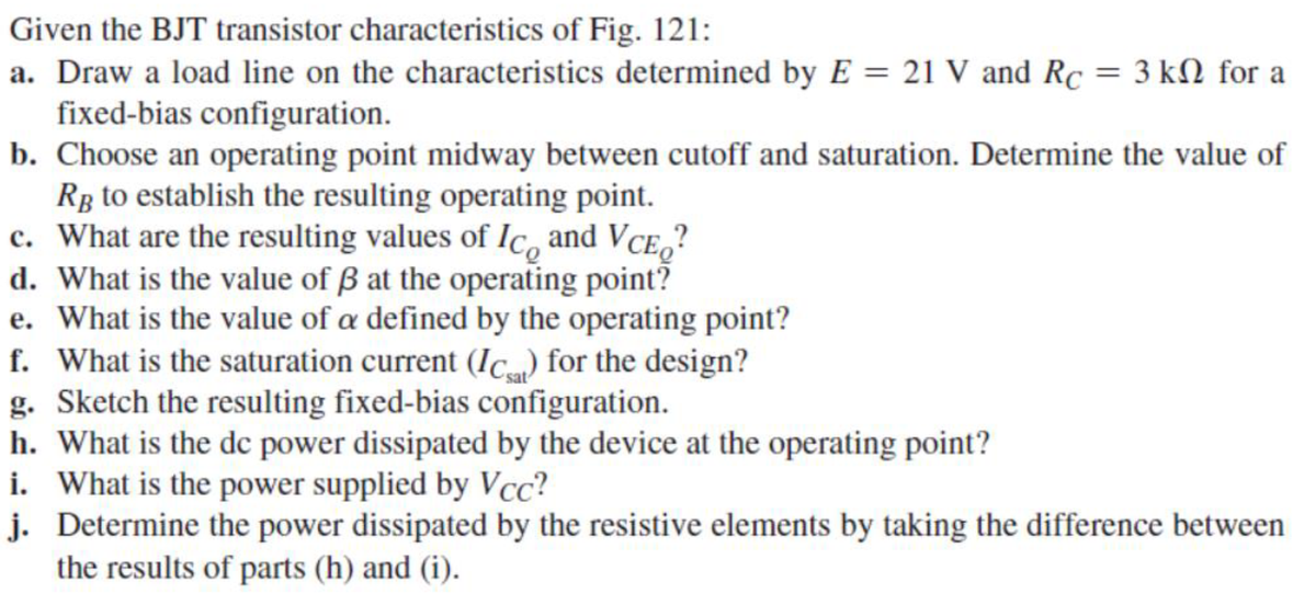
Transcribed Image Text:Given the BJT transistor characteristics of Fig. 121:
a. Draw a load line on the characteristics determined by E = 21 V and Rc = 3 kN for a
fixed-bias configuration.
b. Choose an operating point midway between cutoff and saturation. Determine the value of
Rg to establish the resulting operating point.
c. What are the resulting values of Ic, and VCE,?
d. What is the value of ß at the operating point?
e. What is the value of a defined by the operating point?
f. What is the saturation current (Ic...) for the design?
g. Sketch the resulting fixed-bias configuration.
h. What is the dc power dissipated by the device at the operating point?
i. What is the power supplied by Vcc?
j. Determine the power dissipated by the resistive elements by taking the difference between
the results of parts (h) and (i).
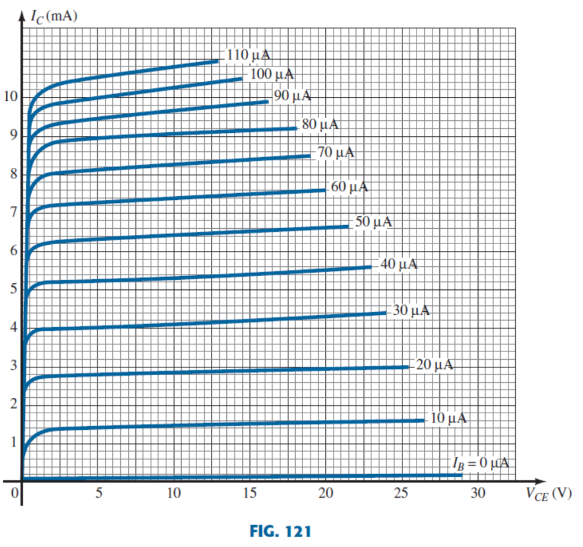
Transcribed Image Text:A Ic(mA)
110 μΑΗ
100 μΑ
10
90 μΑ
80 μΑ
9
70 μΑ
8
60 μΑ.
7
50 μΑ
6.
40 μΑ
5
30 μ.ΑΙ
3
-20 μΑ
10 μΑ
Ig = 0 µµA
5
10
15
20
25
30
VCE (V)
FIG. 121
Expert Solution
This question has been solved!
Explore an expertly crafted, step-by-step solution for a thorough understanding of key concepts.

Step by step
Solved in 2 steps with 1 images

Knowledge Booster


Learn more about
Need a deep-dive on the concept behind this application? Look no further. Learn more about this topic, electrical-engineering and related others by exploring similar questions and additional content below.Recommended textbooks for you
Introductory Circuit Analysis (13th Edition)
Electrical Engineering
ISBN:
9780133923605
Author:
Robert L. Boylestad
Publisher:
PEARSON

Delmar's Standard Textbook Of Electricity
Electrical Engineering
ISBN:
9781337900348
Author:
Stephen L. Herman
Publisher:
Cengage Learning

Programmable Logic Controllers
Electrical Engineering
ISBN:
9780073373843
Author:
Frank D. Petruzella
Publisher:
McGraw-Hill Education
Introductory Circuit Analysis (13th Edition)
Electrical Engineering
ISBN:
9780133923605
Author:
Robert L. Boylestad
Publisher:
PEARSON
Delmar's Standard Textbook Of Electricity
Electrical Engineering
ISBN:
9781337900348
Author:
Stephen L. Herman
Publisher:
Cengage Learning
Programmable Logic Controllers
Electrical Engineering
ISBN:
9780073373843
Author:
Frank D. Petruzella
Publisher:
McGraw-Hill Education

Fundamentals of Electric Circuits
Electrical Engineering
ISBN:
9780078028229
Author:
Charles K Alexander, Matthew Sadiku
Publisher:
McGraw-Hill Education

Electric Circuits. (11th Edition)
Electrical Engineering
ISBN:
9780134746968
Author:
James W. Nilsson, Susan Riedel
Publisher:
PEARSON

Engineering Electromagnetics
Electrical Engineering
ISBN:
9780078028151
Author:
Hayt, William H. (william Hart), Jr, BUCK, John A.
Publisher:
Mcgraw-hill Education,