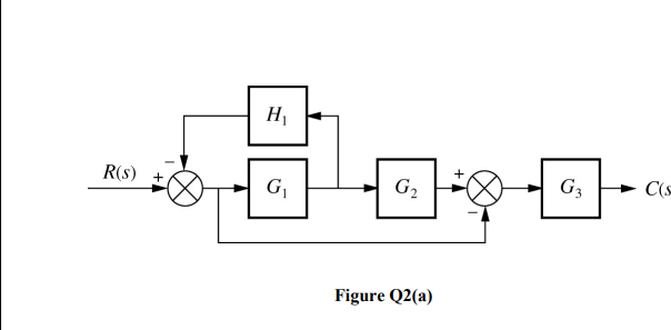
G3 C(s G2 R(s) G Figure Q2(a)


Q: In NMOS, the current flows from a. drain to gate O b. source to drain Oc. source to gate O d. drain…
A:
Q: Determine the current flowing through the LED. (assuming its forward voltage is 2.1 volts) * A D1 D2…
A:
Q: If the load resistance is increased by 25%, the noise voltage will:
A:
Q: Determine the current flowing through the resistor R1. (assume LED forward voltage is 2.1 volts) *…
A: In this question, We need to determine the current flowing through the resistor R1. Current I= V/R…
Q: Which of the following is not a properties of Convolution? O Modulation O Convolution Theorem O…
A: We need to select correct option for statement .
Q: If the internal noise is reduced in a nonideal amplifier, the output signal-to- noise power ratio…
A: The solution is given below Correct option is 1-d 2-c
Q: 4.14 Given a 3 KVA transformer with an efficiency load and unity power factor and a copper…
A: In this question, We need to determine the iron losses if efficiency of the Transformer is given at…
Q: What is the dynamic resistance of a diode if its ID = 1.87 mA?
A: At room temperature the dynamic resistance of diode is given as rd=( 26mV/ID) , for Ge and rd=…
Q: 3im 17m 20m 0.072 3-27A 冬4-52 8.IA 902 12-6V radio repeater 20.4V Solar Parel Wind genemtor
A:
Q: What is the scalar electric field strength 15 mm away perpendicularly from the center of a disk…
A:
Q: 구사 Leee alt) Ia 三10a I,
A: The given circuit diagram is shown below:
Q: Comparing an electric dipole attenna and a magnetic dipole attenna, if the frequency is the same and…
A: According to the question, Comparing an electric dipole antenna and a magnetic dipole antenna, if…
Q: -jue I2 V2 Sind yu
A:
Q: 2. The sequence b(k) = {1, 1, 0, 1, 0, 1} is transmitted at bit rate of Rp =200 b/s using an ASK…
A: According to the question, for an ASK digital system Input data sequence b(k)={1, 1, 0, 1, 0, 1}…
Q: A surge resistor of 4.7 ohm is added to Figure 4-45 in between the rectifiers circuit and the…
A: As the ratio from primary to secondary winding is, 8:1 And we know, Implies, Putting values,
Q: a C: The switch in the circuit above has been in position a for a long time. The variables in the…
A: As per our company guidelines we are supposed to answer only first 3 subpart kindly repost the other…
Q: Suppose that the power delay profile of wireless channel is given by P(t ) = (1 /OT) exp-τ /στ , τ >…
A: A delay spread is the multipath richness in telecommunication. It is the difference between the…
Q: Vout (s) for the two circuits shown below. 6. Wr ite the transfer function, Vin (s) ' R1 R1 R2
A:
Q: Which of the following provides the process transconductance parameter? O a. H„Cox O b. none of the…
A: The solution is given below
Q: 3. Find the Vout and io (a) (b) 20 kQ 8kQ ww 10 kN ww 6 k2 ww- 6k2 1.5 V 2V 4 kN 4 kN 1.2 V
A:
Q: 30 V: 5k0
A: The solution is given below
Q: R= 180 2 120 V 30 mH 1000 Hz coil Solve for VR1 Copy paste these in as needed 2° (No phase angle…
A: The solution is given below
Q: 1. Vertical wind turbines have the highest Betz coefficient T F 2. Wind power is attractive because…
A: 1. Berts coeficient is defined as the ratio of the enerfy which is usefull and the energy which is…
Q: Q3: Determine V, and V2. Use B=1.00 1.6 kN 22 k 2 mA
A:
Q: Determine the voltage across the resistor R1. (assume LED forward voltage is 2.1 volts
A: In this question, We need to determine the the voltage across the resistor R1. (assume LED forward…
Q: If the amplifier gain is tripled, the PLL open-loop gain will: Select your answer. also tripled…
A: Solve the problem
Q: For the circuit of Figure 5.1, calculate the value of VA for each stepped value of VS and place the…
A: The given circuit is shown below:
Q: Write a KCL node equation for the node marked v1 in the circuit below. Put the equation in normal…
A: A circuit diagram is given in the question. The capacitor initial voltage is vC0-=2 Volts and the…
Q: For the point charge Q = 30µc at the origin (0,0,0) . Find the potential difference between (8,6,7)…
A: We need to find out potential at given point .
Q: R2 2K D2 D3 2K In the circuit shown, determine the voltage across resistor R2.
A: As per our guidelines we are supposed to be answer the first question only. Kindly repost the other…
Q: Determine the total flux in the core as given in Figure Q1-3. [Answer: 0 = µNih/ 2t[In (b/a)] b a +…
A: A magnetic core is shown in the question. The core is a toroid with rectangular cross section. We…
Q: ease help me answer with my assignment. What is the difference between the voltage regulation and…
A:
Q: Determine the current flowing through the LED. (assume an LED forward voltage of 2.1 volts) *
A:
Q: An NMOS has a substrate impurity doping concentration of Na =2 x 1016 cm3, a threshold voltage of…
A: NMOS(N-type metal-oxide-semiconductor logic): n-type MOSFETs (metal-oxide-semiconductor field-effect…
Q: 1. Calculate D in rectangular coordinates at point PA(2, –3, 6)produced by a uniform line charge =…
A:
Q: What is the mass and charge of an electron?
A: In this question, We need to determine the mass and charge of electron
Q: A periodic signal x(t) is given below: x(1) t -3 -2 -1 1 2 3 4 14444 1. Determine the fundamental…
A: A periodic signal is a signal which repeats itself in a fixed period of time, where as a non…
Q: -Design a Phase shift oscillator (BJT, mosfet, op-amp choose one) that operate on 1khz -The output…
A:
Q: 10 V 10 V ĮR1 $3.9kn ĮR3 381kn Q1 2N2219 R4 R2 7.9kN .7kΩ
A:
Q: Problem 3. Consider the transfer function G(s) =7+w %3D Does there exist a bounded input such that…
A:
Q: Solve the loop and branch currents using Maxwell's theorem
A:
Q: a R C The switch in the circuit above has been in position a for a long time. The variables in the…
A: As per our company guidelines we are supposed to answer only first 3 subpart kindly repost the other…
Q: find the inductance at A and the resistance
A:
Q: QUESTION 2 Given a unity feedback system with the forward-path transfer function 7 G(s) =-…
A:
Q: interception losses a. include evaporation through flow and stemflow b. consist of only…
A: Answer: b. consist of only evaporation. Explanation: a. include evaporation through flow and…
Q: It's a low-frequency oscillator circuit that's relatively stable and easy to tune, and it's often…
A: The solution is given below
Q: а) Given two inputs, x(t) and y(t) signals as illustrated in Figure 1 and Figure 2, respectively.…
A: Given
Q: The 555 timer is connected in the following circuit. The resistance of the extra resistor is 102,…
A: Since you have posted a question with multiple sub-parts, we will solve the first three subparts for…
Q: iven the differential amplifier shown, determine If1, VRE, and VC1- Vcc=+15V RC1 5 ka RC2 5 k2 Vout…
A:
Q: A unity feedback system is shown in Figure Q1. R(s) C(s) K G() Figure Q1 Given that K(s -4s +8) G(s)…
A: Since you have asked multiple questions in a single request, we will be answering only the first…


Step by step
Solved in 2 steps with 2 images


- The circuit in the visual containing a non-linear element will be analyzed with the Small Signal Analysis method and the VR2 (t) voltage will be calculated. Find the voltage VR2 (t) by calculating the effect of the variable source using the linear model.A cylindrical load cell could be used to measure the wait of a tank. This could be achieved by using number ofstrain gauges with a Wheatstone bridge:bridge refer to how the strain-gauges are put on the load cell.i) clarify the working principle of the design provided, starting from the input (weight) tothe output of the Wheatstone bridge (draw a circuit diagram to show how the signal is converted during the operation of your designDraw the circuit diagram of a differential amplifier using one op amp and resistances as needed. Give the output voltage in terms of the input voltages and resistances.
- Modify the circuit in figure above to get Gain = 4. Provide the modified circuit with its simulation that shows the input and output signals. Please explain how the modification can produce Gain = 4.Derive an expression for the output voltage of the circuit below in terms of the fourinput voltages. Simplify your result as much as possible.Dimension R so that a current of 1A flows through the load to GND. You want to be able to regulate the current to 0, the OP is also supplied from the 15V. What is the requirement for the OP then? ..
- Circuit1( 4 mosfets) Cicruit2( 2 mosfets) The gain of the circuit 1 is -gm1(Ron ll Rop) and the gain of circuit 2 is -Gm(ro1 ll ro2) Combine the gain of these two circuits (drawing the small signal model could help)Perform an ac analysis. Represent the amplifier by its ac equivalent circuit and discuss the input resistance at the base and the output resistance. (You can draw the circuit by hand on paper and can paste the image)Design a circuit using op-amps for following equation. VO = 2V1 − 3V2 − 5V3 + 2V4 − 7V5 Where V1, V2, V3, V4 and V5 are input signals and VO is output signal.