gelner Inas voltage

Power System Analysis and Design (MindTap Course List)
6th Edition
ISBN:9781305632134
Author:J. Duncan Glover, Thomas Overbye, Mulukutla S. Sarma
Publisher:J. Duncan Glover, Thomas Overbye, Mulukutla S. Sarma
Chapter11: Transient Stability
Section: Chapter Questions
Problem 11.8P

Related questions
Question
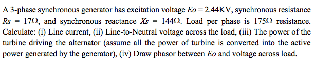
Transcribed Image Text:A 3-phase synchronous generator has excitation voltage Eo = 2.44KV, synchronous resistance
Rs = 170, and synchronous reactance Xs = 1442. Load per phase is 1750 resistance.
Calculate: (i) Line current, (ii) Line-to-Neutral voltage across the load, (iii) The power of the
turbine driving the alternator (assume all the power of turbine is converted into the active
power generated by the generator), (iv) Draw phasor between Eo and voltage across load.
Expert Solution
This question has been solved!
Explore an expertly crafted, step-by-step solution for a thorough understanding of key concepts.

Step by step
Solved in 2 steps with 2 images

Knowledge Booster


Learn more about
Need a deep-dive on the concept behind this application? Look no further. Learn more about this topic, electrical-engineering and related others by exploring similar questions and additional content below.Recommended textbooks for you
Power System Analysis and Design (MindTap Course …
Electrical Engineering
ISBN:
9781305632134
Author:
J. Duncan Glover, Thomas Overbye, Mulukutla S. Sarma
Publisher:
Cengage Learning
Power System Analysis and Design (MindTap Course …
Electrical Engineering
ISBN:
9781305632134
Author:
J. Duncan Glover, Thomas Overbye, Mulukutla S. Sarma
Publisher:
Cengage Learning