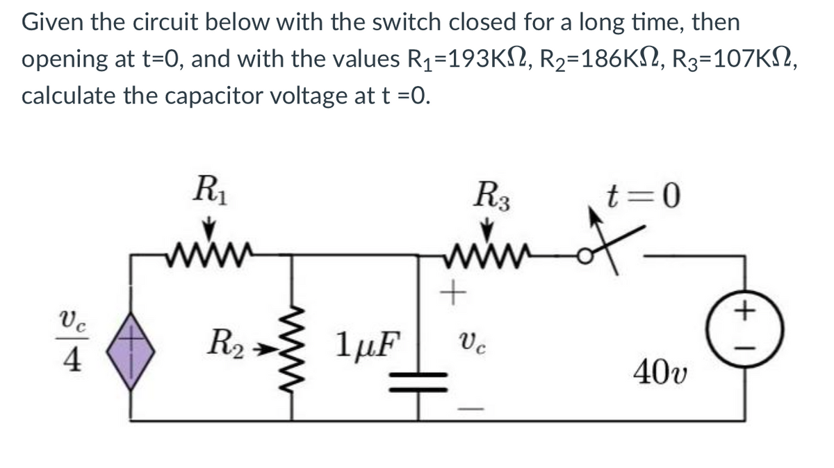
Given the circuit below with the switch closed for a long time, then opening at t=0, and with the values R₁=193KM2, R₂=186KS, R3-107KS, calculate the capacitor voltage at t =0. Vc 4 R₁ www R₂ 1μF R3 mim + Vc t=0 of 40υ (+1


Q: Given the closed-loop system in the figure with C(s) = K and G(s) = (s+2)(s+5) interval of the…
A: A mechanical or electrical device known as a closed-loop control system automatically adjusts a…
Q: EX) is 7 f(t) = 2rect (£) find 2= f(t) graphically
A:
Q: Explain what this matching box is. Describe the parts
A: The given diagrams are shown below. It is asked what is this matching box and also it asked to…
Q: Va + | 40ΚΩ I 30ΚΩ Μ 20kΩ ww 200kΩΣ 220kΩ Μ + Ud + Vo P m • 20kΩ
A: We need to find out the output voltage for given circuit .
Q: Homework of lecture 2 For a selected system, determine whether the system is (1) stable, (2) causal,…
A: In this question we need to check the given system is stable, casual, linear, time invariant and…
Q: In theory, the circuit has a resistance value assigned ONLY to the resistors. In reality, however,…
A: There are three passive elements in the circuits, namely resistor, inductor and capacitor.
Q: (1) Find ia· 1Ω 5V 5A 1Ω 5V 10 Α Μ 1Ω 5V 1Ω Μ 5Α 5V 10 Α 1Ω
A: Given, The circuit diagram,
Q: 2) a) Draw Boolean functions F= x'y+xy', b) then try to draw it using only four NAND gates. 3)…
A: 2. a. The given boolean function is: F=x'y+xy' This boolean expression is for the EX-OR gate. It can…
Q: You are investigating the electrical testing circuits and find that, in an inductive circuit, the…
A:
Q: Based on the figure below, what is the direction of the magnetic force? B O left up down O right
A:
Q: Computer Digital Logic. Design 4 X 1 Multiplexer.
A: The 4 X 1 Multiplexer has 4 inputs and 1 output. The block diagram of the 4 X 1 Multiplexer is shown…
Q: Apply voltage divider rule:VL=RLRS+RLViminso,Vimin=RS+RLRLVLVimin=91Ω+220Ω220Ω×8 voltVimin=311220×8…
A:
Q: In (Figure 1), C₁ = 3.50 μF and Vab = 160 V. The charge on capacitor C₁ is 150 μC and the charge on…
A: In Figure 1, each capacitance C1 is 3.50 μF and Vab=160 V. The charge on the capacitor C1 is 150 μC…
Q: Q2 For t < 0s, the switch has been opening and closing (and the capacitor may not have reached…
A:
Q: Hello there. To start off, I AM BLIND AND CAN NOT READ IMAGES YOU MAY ATTEMPT TO RESPOND WITH.…
A:
Q: Consider the circuit shown below. The SCS has a triggering voltage of 1 V and holding current of 4…
A: Given SCS trigger voltage, VT =1 V holding current , IH =4 mA R1 =500 Ω R2 =1kΩ Note: Gate input…
Q: 24. Let D = (10r2 + 5e )a, C/m²: (a) Find p, as a function of r. (b) Find the total charge lying…
A:
Q: Ex calculate the energy considered in the signal f(t) = at ult in both time domain and e Frecency…
A:
Q: What is the gain (Vo/Vs) of the following system, if all resistors are equal to 100?? O 100 02 O www…
A: From figure , input is connected at the non inverting terminal of opamp , so it is a non inverting…
Q: A ferromagnetic ring has a uniform cross-sectional area of 2000 mm² and a mean circumference of 1000…
A: Cross sectional area = 2000 mm2 = 2000×10-6 m2 Mean circumference = 1000 mm = 1000×10-3 m Frequency…
Q: In the circuit shown in Fig. P6.58, the transistor has β =50. Find the values of VB, VE, and VC, and…
A: In the given diagram , we need to find DC parameter of the given circuit.
Q: A certain load comprises 12 +j8 Ω in parallel with j5Ω. Determine the overall power factor
A: Given that ZL1=12 +j8 Ω ZL2=j5 Ω
Q: Use five-bit 1's and 2's complement representations, perform the following operations. Verify your…
A: Given: a) 9+4 b) -9+4 To find: we have to perform above operations using 1's and 2's complement…
Q: You are working on a design for an electromagnetic compass. A single circular loop of wire with an…
A: Given that, Area of circular loop (A) =1.6mm2, , Current in the loop (I) =4.7μA, Magnetic field of…
Q: 7. (20 pts) Simplify the given logic circuit diagram in Figure 2 using minimum number of gates for…
A:
Q: Problem 9. An alternating voltage is given by 282.8 sin 314t volts. Find (a) the rms voltage, (b)…
A: Given data:-v=282.8sin314t voltFind:-a. rms voltageb. frequencyc. instantaneous value of voltage…
Q: Consider the circuit below. For t 2 s. Write the equation. 2 V red A-meter black 1 ia 2 6V X = 4A…
A: We need to find out the current for given circuit , first we will find out the current through…
Q: tion: Suppose a discrete-time LTI system is characterized by the following system func- 2-212-1 21 2…
A:
Q: Consider a feedback control system with loop transfer fucntion K (1+0.5s) s(1+s) (1+2s) G(s)H(s) =…
A: For the given feedback system with loop transfer function: GsHs=k1+0.5ss1+s1+2s The type of closed…
Q: tion: Suppose a discrete-time LTI system is characterized by the following system func- 2-212 2 H(z)…
A:
Q: QUESTION 4 If the maximum energy stom 270 0210 850
A: Given data, Energy E= 3 mJ. Circuit diagram is given as
Q: Question 1: Using circuit in Figure 3 of laboratory #5 if the pulse generator has a symmetric square…
A: The circuit is as shown below,
Q: Solve the linear difference equation un+2-7un+1 + 10un = 16n,
A: Given: The difference equation, un+2-7un+1+10un=16 n, To solve: Given difference equation. Note:…
Q: 7.76 The current source in the network in Fig. P7.76a is defined in Fig. P7.76b. The initial voltage…
A: The circuit can be analysed by considering the state of the circuit at t<0, t between 0 to 4.5…
Q: tion: Suppose a discrete-time LTI system is characterized by the following system func- 2-212-1 ibl.…
A:
Q: Q1: The total harmonic distortion of a closed loop system is 5%. Distortion without feedback is 10%.…
A: Distortion of a closed loop system DHF = 5% Distortion without feedback = 10%
Q: An OpAmp can output more than the power source, depending on the circuit connected to it. True False…
A:
Q: Example S Find the F.T of the triangular pulse f(t) = A Tri (1)
A: Triangular Function Definition f(t)= Tri(t)=1-t, t<10, Otherwisef(t)= Tri(tT)=1-tT, tT<10,…
Q: Given G₁ = 4(s+8) /(s+3)(s+7) and G₂=2s /(s+10) function write an m-script to determine the final…
A: Given that G₁ = 4(s+8) /(s+3)(s+7) G₂=2s /(s+10)
Q: PRACTICE EXERCISE 8.7 In a certain region (u = 4.6μ), B = 10ea₂ mWb/m² find: (a) Xm² (b) H, (c) M.…
A:
Q: www ww R₂ C₁ R₁ C₂ 2₁ Rf R3 + R₁ D₁ C3 Vout
A: The above circuit is the circuit of the Wein bridge for the automatic gain control. The Zener diode…
Q: The cross-sectional area of a transform limb is 80 cm² and the volume of the transformer ca is 5000…
A:
Q: Consider the causal discrete-time LTI system described by the following constant coefficient…
A:
Q: 1a)Analyze the circuit in Figure 1, consider R = 10 k and C= 10 nF. Obtain the mathematical equation…
A: Given: A RC circuit with R=1 KΩ and C=10 nF, f = 4 KHz ⇒ω=2π×4×103=8000π, To find: a) Equivalent…
Q: A (stable) linear system has the frequency response depicted in the following Bode diagram. Bode.pdf…
A: Given, A stable LTI system has frequency response of We need to determine the steady state…
Q: What is the lighting and receptacle demand load for an 1000 sq. m office space with one hundred ten,…
A:
Q: Consider the discrete-time LTI system shown below with h(n) = ()u(n). (a) Determine the system…
A: Given: h(n)=13nu(n) To find: a) y(n) when x(n)=u(n+4)-u(n-8) b) Impulse response of the system.
Q: Problem 1: The circuit shown in the figure is in a dark room. When the bright light is turned on,…
A: SCR (Silicon controlled rectifier ) or Thyristor is a semi-controlled power switch in which its on…
Q: Question 3: (For practice only) Solve the given block diagram using Block diagram reduction and…
A:
Q: Problem 10 Find the Inverse Fourier transforms of the following functions: 1 (a) X(w) = 7+ jw…
A: As per Bartleby guideline we need to answer the first three question only. Kindly repost the rest…
Given the circuit below with the switch closed for a long time, then opening at t=0, and with the values R1=193KΩ, R2=186KΩ, R3=107KΩ, calculate the capacitor voltage at t =0.


Trending now
This is a popular solution!

Step by step
Solved in 2 steps with 1 images

- In the circuit of the figure, the switch S has been in position a for a long time; when the current through the inductor is maximum, the switch changes to position b (this instant is taken as t = 0). If the current source is iS(t) = 2.1213 cos (100πt + π/ 4). Determine: i) the value of R2 so that at t = 4 mS the current iL (t = 4mS) = 1 A. ii) The expression for the inductor current iL(t) t> 0 iii) the value of iL(t) at t = 0. iv) the expression of the inductor voltage vL(t) t> 0. v) the value of vL(0).The switch is closed for a very long time. At time 0s, the switch is opened. a.) Solve for vo(t) when t ≥ 0 if R = 1.6 kiloohms. b.) Solve for R=Rcrit that makes response critically underdamped, then solve for vo(t) t ≥ 0 if R=Rcrit.In the circuit shown, the switch is open, and the capacitors are uncharged. At t=0, the switch S is closed. Find the equivalent resistance of the circuit at t=0. R1=2R, R2=R, C1=C, C2=2C.
- Please answer ASAP and I'll upvote, thank you. In the given circuit, switch S1 is in position A and switch S2 is open. Both switches are in these states for a very long time. At t=0, switch S1 moves from position A to B while switch S2remains open. 10ms after switch S1 moves to position B, switch S2 is closed and remains closed for 20ms only. Determine the expressions for the inductor current for 0≤t<10ms, 10ms≤t<30ms, 30ms≤t<∞, and determine the time (in ms) after switch S1 moves to position B is the current in the inductor equivalent to 30% of the initial value (at ?=0).An electric circuit contains a 1-H inductor, a 4-$ resistor, and a voltage source of sin t. The resulting differential equation relating the current i and the time t is di / dt + 4i = sin t. Find i after 0.5 s by Euler's method with At= 0.1 s if the initial current is zero. Solve the equation exactly and compare the values. Use Euler's method to find i after 0.5 s. iapprox = A Round the final answer to four decimal places as needed. Round all intermediate values to nine decimal places as needed.)(a) Specify v1(0) and v2(0) for determining the equivalent circuit involving the capacitors for t≥0. : (b) At t0=0.2 s, determine the currennt i(t0=0.2 s): (c) At t0=0.2 s, determine υ1(t0) and υ2(t0):
- Question 6 Given a formula for i(t)=10sin(200pit+pi/8) across a capacitor (C=5microfarads). Find the expression of the voltage v(t) across the capcitor. Where Im confused is after integrating the Current and dividing it by C=5microfarads do we need to add +K at the end of the expression? Full explainthe this question very fast solution sent me step by step Don't ignore any part all part work u Text typing work only not allow paper work ......*The switch in the circuit in (Figure 1) has been in the left position for a long time. At t = 0 it moves to the right position and stays there.* Pt A. Write the expression for the capacitor voltage, v(t), for t≥0 Pt B. Write the expression for the current through the 40 kΩ resistor, i(t), for t≥0+Capacitor C is initially uncharged at t=0 (when switch S is toggled from open to closed). What is the change in the voltage drop V2 across resistor R2 from t=0 to t = ∞ (meaning a large number of time constants later)? The values are: ε= 1.4 kV, C = 4.5 µF, R1 = 0.71 M Ω, R2 = R3 = 0.58 M Ω. Note that 1 M Ω= 106 ohms. Give your answer in V.
- given the circuit below , find and plot the current ix(t) for t>0s A=3A resistors=2 ohms each anc capacitor=1/4F voltage source is 3ix. solve in great detail.The two parallel inductors shown are connected across the terminals of a black box at t=0. The resulting voltage v for t>0 is known to be 12e−t V. It is also known that i1(0)=2 A and i2(0)=4 A. a. Replace the original inductors with an equivalent inductor and find i(t) for t≥0. b. Find i1(t) for t≥0. c. Find i2(t) for t≥0. d. How much energy is delivered to the black box in the time interval 0≤t<∞? e. How much energy was initially stored in the parallel inductors? f. How much energy is trapped in the ideal inductors? g. Show that your solutions for i1 and i2 agree with the answer obtained in (f).Closed loop poles in a second order system -3 + 4j and -3-4j If so, what is the damping rate of the system? 3/44/35/45/33/5one4/50