Given the following figure and single force (FEH 200 lb): (a) Calculate the vector form for the moment about point D- Mp[ (b) Calculate the scalar form for the moment about axis CD- McD 10 in 30 in, 7.5 in. E 7.5 in. 10 in. 10 in. H
Given the following figure and single force (FEH 200 lb): (a) Calculate the vector form for the moment about point D- Mp[ (b) Calculate the scalar form for the moment about axis CD- McD 10 in 30 in, 7.5 in. E 7.5 in. 10 in. 10 in. H

International Edition---engineering Mechanics: Statics, 4th Edition
4th Edition
ISBN:9781305501607
Author:Andrew Pytel And Jaan Kiusalaas
Publisher:Andrew Pytel And Jaan Kiusalaas
Chapter6: Beams And Cables
Section: Chapter Questions
Problem 6.18P: For the ladder in Prob. 6.17, find the internal force system acting on section 2, assuming that x <...

Related questions
Question
i need the answer quickly
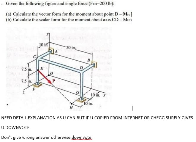
Transcribed Image Text:. Given the following figure and single force (FEH-200 lb):
(a) Calculate the vector form for the moment about point D- Mp [
(b) Calculate the scalar form for the moment about axis CD- MCD
10 in.
30 in.
B
7.5 in.
E
7.5 in.
G
10 in. X
10 in.
H
|
NEED DETAIL EXPLANATION AS U CAN BUT IF U COPIED FROM INTERNET OR CHEGG SURELY GIVES
U DOWNVOTE
Don't give wrong answer otherwise downvote
Expert Solution
This question has been solved!
Explore an expertly crafted, step-by-step solution for a thorough understanding of key concepts.

This is a popular solution!

Trending now
This is a popular solution!

Step by step
Solved in 2 steps with 2 images

Recommended textbooks for you
International Edition---engineering Mechanics: St…
Mechanical Engineering
ISBN:
9781305501607
Author:
Andrew Pytel And Jaan Kiusalaas
Publisher:
CENGAGE L
International Edition---engineering Mechanics: St…
Mechanical Engineering
ISBN:
9781305501607
Author:
Andrew Pytel And Jaan Kiusalaas
Publisher:
CENGAGE L