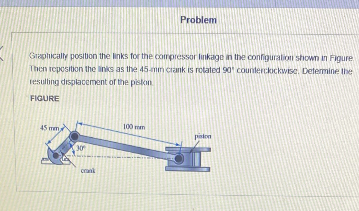
Graphically position the links for the compressor linkage in the configuration shown in Figure, Then reposition the links as the 45-mm crank is rotated 90° counterclockwise. Determine the resulting displacement of the piston. FIGURE 45 mm 100 mm piston 30 crank
Graphically position the links for the compressor linkage in the configuration shown in Figure, Then reposition the links as the 45-mm crank is rotated 90° counterclockwise. Determine the resulting displacement of the piston. FIGURE 45 mm 100 mm piston 30 crank

International Edition---engineering Mechanics: Statics, 4th Edition
4th Edition
ISBN:9781305501607
Author:Andrew Pytel And Jaan Kiusalaas
Publisher:Andrew Pytel And Jaan Kiusalaas
Chapter8: Centroids And Distributed Loads
Section: Chapter Questions
Problem 8.73P

Related questions

Question
100%
Transcribed Image Text:Problem
Graphically position the links for the compressor linkage in the configuration shown in Figure.
Then reposition the links as the 45-mm crank is rotated 90° counterclockwise. Determine the
resulting displacement of the piston.
FIGURE
45 mm
100 mm
piston
30
crank
Expert Solution
This question has been solved!
Explore an expertly crafted, step-by-step solution for a thorough understanding of key concepts.

This is a popular solution!

Trending now
This is a popular solution!

Step by step
Solved in 4 steps with 4 images

Knowledge Booster


Learn more about
Need a deep-dive on the concept behind this application? Look no further. Learn more about this topic, mechanical-engineering and related others by exploring similar questions and additional content below.Recommended textbooks for you
International Edition---engineering Mechanics: St…
Mechanical Engineering
ISBN:
9781305501607
Author:
Andrew Pytel And Jaan Kiusalaas
Publisher:
CENGAGE L
International Edition---engineering Mechanics: St…
Mechanical Engineering
ISBN:
9781305501607
Author:
Andrew Pytel And Jaan Kiusalaas
Publisher:
CENGAGE L