gure 1 of 1 > 2 m B D 1 m 2 m 1 m

Principles of Foundation Engineering (MindTap Course List)
8th Edition
ISBN:9781305081550
Author:Braja M. Das
Publisher:Braja M. Das
Chapter14: Sheet-pile Walls
Section: Chapter Questions
Problem 14.5P

Related questions
Question
Please complete both questions using the method of joints to find all the forces with in every member including if they are compression or tension.
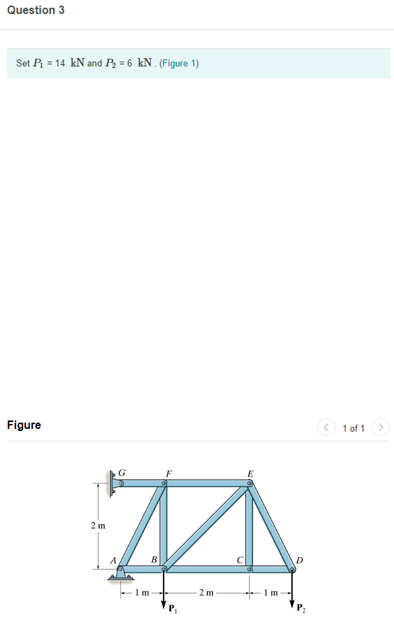
Transcribed Image Text:Question 3
Set P = 14 kN and P = 6 kN . (Figure 1)
Figure
1 of 1>
G
F
2 m
A
B
2 m
1 m
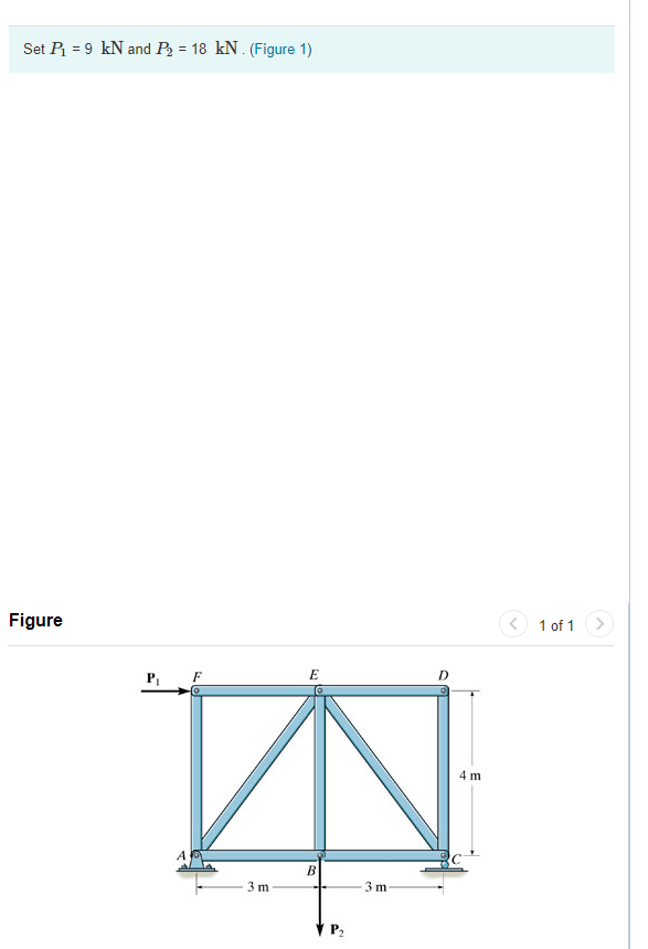
Transcribed Image Text:Set P = 9 kN and P = 18 kN . (Figure 1)
Figure
1 of 1 >
E
P,
F
4 m
В
3 m
3 m
V P2
Expert Solution
This question has been solved!
Explore an expertly crafted, step-by-step solution for a thorough understanding of key concepts.

Step by step
Solved in 8 steps with 7 images

Knowledge Booster


Learn more about
Need a deep-dive on the concept behind this application? Look no further. Learn more about this topic, civil-engineering and related others by exploring similar questions and additional content below.Recommended textbooks for you
Principles of Foundation Engineering (MindTap Cou…
Civil Engineering
ISBN:
9781305081550
Author:
Braja M. Das
Publisher:
Cengage Learning
Principles of Foundation Engineering (MindTap Cou…
Civil Engineering
ISBN:
9781305081550
Author:
Braja M. Das
Publisher:
Cengage Learning