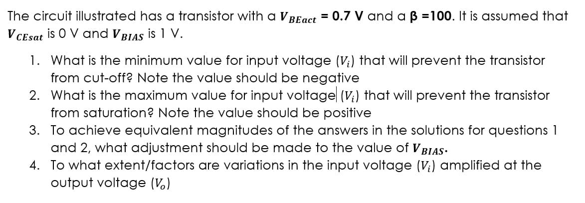
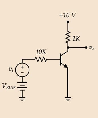
The circuit illustrated has a transistor with a VBEact = 0.7 V and a ß =100. It is assumed that is 0 V and VBIAS is 1 V. V CEsat 1. What is the minimum value for input voltage (V;) that will prevent the transistor from cut-off? Note the value should be negative 2. What is the maximum value for input voltage (V₁) that will prevent the transistor from saturation? Note the value should be positive 3. To achieve equivalent magnitudes of the answers in the solutions for questions 1 and 2, what adjustment should be made to the value of VBIAS. 4. To what extent/factors are variations in the input voltage (Vi) amplified at the output voltage (V)
The circuit illustrated has a transistor with a VBEact = 0.7 V and a ß =100. It is assumed that is 0 V and VBIAS is 1 V. V CEsat 1. What is the minimum value for input voltage (V;) that will prevent the transistor from cut-off? Note the value should be negative 2. What is the maximum value for input voltage (V₁) that will prevent the transistor from saturation? Note the value should be positive 3. To achieve equivalent magnitudes of the answers in the solutions for questions 1 and 2, what adjustment should be made to the value of VBIAS. 4. To what extent/factors are variations in the input voltage (Vi) amplified at the output voltage (V)

Electricity for Refrigeration, Heating, and Air Conditioning (MindTap Course List)
10th Edition
ISBN:9781337399128
Author:Russell E. Smith
Publisher:Russell E. Smith
Chapter12: Electronic Control Devices
Section: Chapter Questions
Problem 3RQ: Diodes and rectifiers allow current to _________.
flow in one direction only
flow in both...

Related questions

Question
please show clear solution for the given questions
Transcribed Image Text:The circuit illustrated has a transistor with a V
V CEsat is O V and VBIAS is 1 V.
BEact = 0.7 V and a ß =100. It is assumed that
1. What is the minimum value for input voltage (V₁) that will prevent the transistor
from cut-off? Note the value should be negative
2. What is the maximum value for input voltage (V;) that will prevent the transistor
from saturation? Note the value should be positive
3. To achieve equivalent magnitudes of the answers in the solutions for questions 1
and 2, what adjustment should be made to the value of V BIAS.
4.
To what extent/factors are variations in the input voltage (V;) amplified at the
output voltage (V)
Transcribed Image Text:Vi
V BIAS
+ 1
HilHi
10K
w
+10 V
1K
Vo
Expert Solution
This question has been solved!
Explore an expertly crafted, step-by-step solution for a thorough understanding of key concepts.

This is a popular solution!
Step 1: Given that
VIEWStep 2: 1) Calculation of minimum voltage of vi to prevent the transistor from cutoff
VIEWStep 3: 2) Calculation of the maximum voltage of vi to prevent the transistor from saturation mode
VIEWStep 4: 3) Adjustment in VBIAS to achieve the given requirement in part (1) and part (2)
VIEWStep 5: 3) DC analysis of the amplifier
VIEWStep 6: Calculation of voltage gain of the amplifier
VIEWSolution
VIEW
Trending now
This is a popular solution!

Step by step
Solved in 7 steps with 3 images

Follow-up Questions
Read through expert solutions to related follow-up questions below.
Follow-up Question
Hello! I just wanted to ask how did you get VT = 26m in the Emitter dynamic resistance in step 5? Also in step 6, is the KVL in Vi wrong? since Vi = -(IBR10k + IBBre) which makes Vo/Vi = (1k)(100) / -(86700+867) = -1.14
Av = -1.14
Hoping for your response. Thank you!
Solution
Knowledge Booster


Learn more about
Need a deep-dive on the concept behind this application? Look no further. Learn more about this topic, electrical-engineering and related others by exploring similar questions and additional content below.Recommended textbooks for you
Electricity for Refrigeration, Heating, and Air C…
Mechanical Engineering
ISBN:
9781337399128
Author:
Russell E. Smith
Publisher:
Cengage Learning
Electricity for Refrigeration, Heating, and Air C…
Mechanical Engineering
ISBN:
9781337399128
Author:
Russell E. Smith
Publisher:
Cengage Learning