Hilt 20V RI DI 12 RI RJ 0.5k Calculate the DC operating point of the circuit. The diodes have the model parameters: 1pA: n-1.5 T-300 K
Hilt 20V RI DI 12 RI RJ 0.5k Calculate the DC operating point of the circuit. The diodes have the model parameters: 1pA: n-1.5 T-300 K

Delmar's Standard Textbook Of Electricity
7th Edition
ISBN:9781337900348
Author:Stephen L. Herman
Publisher:Stephen L. Herman
Chapter30: Dc Motors
Section: Chapter Questions
Problem 6RQ: What is CEMF?

Related questions
Question
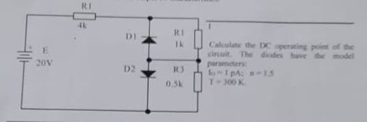
Transcribed Image Text:20V
RI
4k
DI
D2
Ik
R3
0.5k
Calculate the DC operating point of the
circuit. The diodes have the model
parameters
lo-1 pA;
-15
300 K
Expert Solution
This question has been solved!
Explore an expertly crafted, step-by-step solution for a thorough understanding of key concepts.

Step by step
Solved in 3 steps with 32 images

Knowledge Booster


Learn more about
Need a deep-dive on the concept behind this application? Look no further. Learn more about this topic, electrical-engineering and related others by exploring similar questions and additional content below.Recommended textbooks for you
Delmar's Standard Textbook Of Electricity
Electrical Engineering
ISBN:
9781337900348
Author:
Stephen L. Herman
Publisher:
Cengage Learning
Delmar's Standard Textbook Of Electricity
Electrical Engineering
ISBN:
9781337900348
Author:
Stephen L. Herman
Publisher:
Cengage Learning