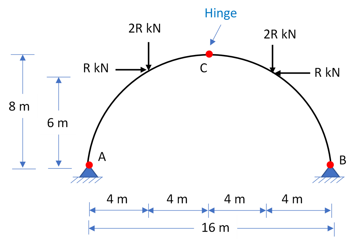
Hinge 2R kN 2R kN R kN C R kN 8 m 6 m A B 4 m 4 m 4 m 4 m 16 m


Q: Consider the following frame ABC with the reactions at A as shown in the figure below. Draw the…
A:
Q: Problem 1- The beam shown below is in equilibrium when subjected to forces presented. Determine the…
A:
Q: 5. Determine the horizontal and vertical components of reaction at the roller support A, and fixed…
A: Answer:- By the equation of equilibrium we can calculate the value of reaction at…
Q: Compute for the following: Vertical Reaction on A, kN Horizontal Reaction on A, kN Moment…
A:
Q: Homework: The pin-connected structure of Figure below has the 2400 N.mm moment applied to member…
A:
Q: Calculate the reactions in the given beam 15 kN 4.8m 3.4m 7.2m A B 9 kN/m Vertical Reaction on B, kN…
A:
Q: 30 kN 10 kN/m A 6 m 2 m 3 m
A:
Q: Using Three-Moment Equation, determine the reactions and draw the shear diagram and moment diagram 3…
A: Degree of indeterminacy = 4. Hence, 4 equations are required to solve moments. Steps for Analysis:…
Q: 6 kips 16 kips B 6 ft 3 ft 2 ft '2 ft
A:
Q: What is the vertical reaction at E in kN.m? Solve for the support reaction of the beam shown in the…
A: A loaded fixed beam with internal hinges has been given and it has been asked to determine Vertical…
Q: 25. What is the reaction at 20 kNím 60AN support B? 120 AN - m 26. What is the maximum shear force?…
A:
Q: 45 k 1.8 k/ft A -B D Liont1ont 10 ft -30 ft- -10 ft El = constant
A:
Q: Determine the reactions at A, B and C. Support B s mm. Take E 200 GPa and I = 300 (106) mm4. 10 kN/m
A:
Q: What is the vertical reaction at E in kN.m? Solve for the support reaction of the beam shown in the…
A:
Q: For the beam shown, calculate the reactions. Calculate the moment at point C. Also, calculate the…
A: Given data in question Simply supported beam UDL Point load To find out Reactions Moment at C…
Q: Problem 2 Solve the reactions for the frame and draw the shear & moment diagram for each member. 22…
A: Apply Equilbrium equation. RE is less because loading is try to rotate the structure about E hence…
Q: 100 kN 10 kN/m A SC 12 m 6 m 21 E= constant %3D
A:
Q: c) For the beam shown Figure Q1.c Calculate the value and directions of the reactions Calculate and…
A:
Q: Solve for the following: a. What is the shear at C? b. What is the shear at D? c. What is the moment…
A: Hi! Thank you for the question, As per the honor code, we are allowed to answer three sub-parts at a…
Q: Determine the reactions for the beam shown using three-moment equation. 35 k 1 k/ft 2 k/ft A C 10'…
A:
Q: Solve the frame approximately using Portal Method. 30KN d 1. 6m 60KN k 6m 72KN 8m TITT 10m 12m 10m…
A:
Q: 35 k 1 k/ft 2 k/ft E A C -10 ft– -10 ft- -10 ft– -20 ft- EL= constant
A:
Q: . a) a) For the beam shown Figure Q1.a Calculate the value and directions of the reactions Calculate…
A: Given data in question Simply supported beam Span length Point loads UDL To find out Reactions…
Q: D 16' w = 1 kip/ft w = 1 kip/ft B_ C w = 1 kip/ft 20-
A:
Q: A. Find the reaction at support B (RB) B. Find the reaction at support B (MB) C. Draw the shear…
A: Draw FBD:
Q: Question 2) Calculate the support reactions at point A and B, and the forces at the hinges (C, D and…
A:
Q: 15 A. Find the reaction at support A (RA) B. Find the reaction at support C (Rc) C. Draw the shear…
A: Draw FBD:
Q: Neglecting the mass of the beam, compute the reactions at A and B. 600 lb 150 lb/ft 7200 lb ft Fon-…
A:
Q: Solve the frame approximately using Portal Method.
A:
Q: Find the reactions at supports A and C. 240 240 600 N 40 18 kg 600 N Dimensions in mm 120
A: Find the reactions at supports A and C.
Q: find the reactions in the frame below using the momen distribution method. there is a concentrated…
A:
Q: calculate the reactions using static equilibrium Please show all steps + FBD 1.0 kN/m 7 kN B 3.0 m
A:
Q: Solve for the reactions and draw V-M diagrams using D.I. Method and/or Force Method 100 kN 10 kN/m A…
A:
Q: Determine the reactions and draw the shear and moment diagrams for the following structure by using…
A:
Q: 4m 4m Problem #8: 3m 5KN 3m B 1.5m 8KN 1.5m C 2m 2m
A: Find support reaction. Joint B is pin joint so moment from either side of is zero.
Q: 1200 N 245 N/m C 2m 2m 2m 2m
A:
Q: 20 kN/m 100 kN | 15 kN.m 5 kN/m 5 m 2 m 2 m
A:
Q: Situation 5: A 6-m long ladder weighing 600 N is shown. is required to determine the horizontal…
A:
Q: P y Wo A Мо C D E d
A:
Q: Determine the reactions and draw the shear and bending moment diagram for the frame shown. 37.5 kN/m…
A:
Q: Determine the reactions for the beam shown in Figure Q6-B. El is constant. (Use the Moment…
A:
Q: 15 kN/m A 7 m 7 m-
A: Given:- udl=15kN/m EI=constant To find:- The reactions Draw the shear and bending moment diagrams
Q: Q5: Determine the reactions at the supports A and B for the Figure shown below, due to the applied…
A: Here we have to determine the reaction forces at supports,NA and NB
Q: frame shown in Figure a Sketch the free body diagram and calculate the support reactions of the…
A:
Q: Problem 1-find the reactions and complete the load diagram. Draw the shear force and bending moment…
A: ASKED: To determine the support reactions and draw the shear and moment diagram. The support…
Q: For the frame shown below, determine the degree of indeterminacy and compute the reactions at D.…
A:
Q: 2 kN/m 3 kN/m 4 m 3 m
A: This is the simply supported beam with one side overhang. to find reaction at any support basic…
Q: Q5: Determine the reactions at the supports A and B for the Figure shown below, due to the applied…
A:
Determine the reactions and sketch the moment diagram.
where R = 11KN


Trending now
This is a popular solution!

Step by step
Solved in 2 steps


- A pipe column is braced to prevent bending and buckling. It is subjected to a compressive load of 1,000 kN E= 200 GPa Length= 4 meters and outside diameter= 250 mm. Find the required column thickness if the allowable shortening of the column is 0.8 mm a. 18.75mm c. 37.44mmb. 11.40mm d. 41.25mmA steel plate 375mm x 16mm thick is bolted by four bolts placed symmetrically to form a single lap joint. The bolts are spaced horizontally at a distance of 140mm and vertically at a distance of 150mm. If the diameter of bolt is 20 mm, calculate the design tensile strength in KN based on net section fracture considering a straight vertical path of failure Use Fy=248MPa and Fu=400MPa a) 1339.2 b) 1569.6 c)2092.8 d) 1488M13
- Help! F1: i: -27.0lbs k: -8.0 lbs F2: i: -82.0lbs M: k: -32.0 lbs*ftA built-up section consisting of W 350 x 90 with two 12 – mm plates welded to form a box section as shown in figure. The section is used as a column 10 meters long. The column is fixed at both ends, and braced at mid height about the weak axis (Y-axis). Use Fy = 248 MPa. Properties of W350x90: bf=250mm tf=16.4mm d=350mm tw=9.5mm Ix=226x10^6 mm^4 Iy=44.54x10^6 mm^4 A=11,550 mm^2 a. Determine the effective slenderness ratio of the column with respect to lateral buckling about the x-axis. b. Determine the effective slenderness ratio of the column with respect to lateral buckling about the y-axis. c. Determine the axial load capacity of the column in kN.Q2: Work out the quantity of steel in a 7m long simply supported beam of size 350 X 600mm overall. Bottom bar: 4 – 12mm diameter straight bars. Anchor bar: 2 – 12mm diameter straight bars, stirrups 10mm diameter @ 250mm c/c throughout the length of the beam. Clear cover as 25mm on all sides.
- To reinforce a column in an existing structure, two channels are welded to the W 12 x 50 column section as shown in the figure. Effective length of column with respect to each axis is 4.8 m. Kx = Ky = 1.0 Properties of W12 x 50 A = 9484 mm2 rx = 131.57 mm ry = 49.78 mm Ix = 164 x 106 mm4 Iy = 23 x 106 mm4 Fy = 345 MPa d = 309.63 mm Properties of C6 x 13 A = 2471 mm2 Ix = 7.24 x 106 mm4 Iy = 0.44 x 106 mm4 bf = 54.79 mm x = 13.06 mm (centroid from the outer side of the web) a. Determine the critical slenderness ratio. b. Determine the design strength of the column section. (kN in LRFD)column section = ISHB 450 Bracket plate thickness in mm =11 p=450KN E=330mm p=55mm bolt size =M20A steel column W300 x 203 kg/m section is used as to support an aial load. A=25740mm^2 Tw = 20mm. Fy= 415 Mpa Tf = 32mm. Lu= 4m d = 340mm. Ix=5.16*10^ 8 mm^4 Iy= 1.65*10^8mm^4 E = 200GPA k = 1.0 Sidesway is prevented. Determine the ultimate design capacity of Column using NSCP 2015. Use Phi= 0.9. 7718.11kN C. 8575.88 kN 333.17 kN D. 20356.06kN
- Complete Table P4.2. For a member where a deflection criterion controls,which material would require a larger cross section? What about for a member. where tension controls? Mild Steel 7178 T76 AluminumYield StrengthUltimate StrengthModulus of ElasticityA solid aluminum alloy [E=69E=69 GPaGPa; α=23.6×10⁻⁶/C∘α=23.6×10-6/C∘] rod (1) is attached rigidly to a solid brass [E=115E=115 GPaGPa; α=18.7×10⁻⁶/C∘α=18.7×10-6/C∘] rod (2), as shown in the figure. The compound rod is subjected to a tensile load of P=6.7P=6.7 kNkN. The diameter of each rod is 1111 mmmm. The rods lengths are L1=475L1=475 mmmm and L2=675L2=675 mmmm. Compute the change in temperature required to produce zero horizontal deflection at end C of the compound rod.To prevent excessive deflection of a 3 meter long cantilever beam subjected to load of 2kN/m, its free end is attached to a tension rod.Beam Properties: A= 1900 mm2 E= 200 GPa I= 5.12x106 mm4 What is the maximum deflection before attaching the tension rod.a. 19.78 mm b. 21.62 mmc. 33.33 mm d. 66.67 mm If the resulting tensile in the rod is 2.5 kN when attached to the beam, find the maximum moment at the fixed enda. -7.5 kN-m b. -9.25 kN-m c. -2.75 kN-m d. 1.5 kN-m Determine the maximum span moment if the tension in the ros id 2.5 kNa. 0.3725 kN-m b. 8.1275 kN-m c. 1.5625 kN-m d. 3.5025 kN-m