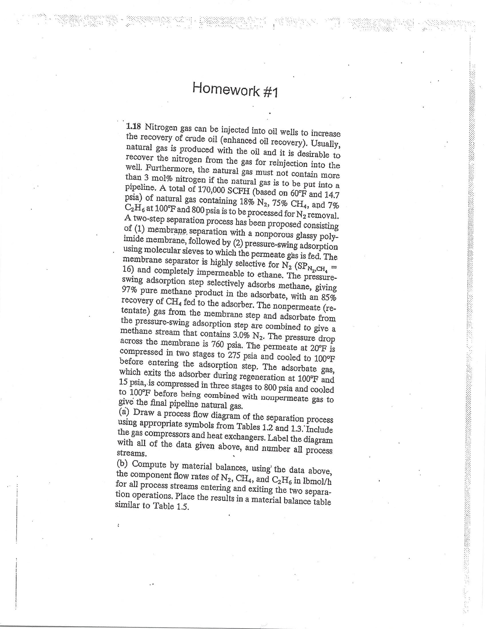
Homework #1 1.18 Nitrogen gas can be injected into oil wells to increase the recovery of crude oil (enhanced oil recovery). Usually, natural gas is produced with the oil and it is desirable to recover the nitrogen from the gas for reinjection into the well. Furthermore, the natural gas must not contain more than 3 mol% nitrogen if the natural gas is to be put into a pípeline. A total of 170,000 SCFH (based on 60°F and 14.7 psia) of natural gas containing 18% N2, 75% CH4, and 7% C2Hs at 100°F and 800 psia is to be processed for N2 removal. A two-step separation process has been proposed consisting of (1) membrane, separation with a nonporous glassy poly imide membrane, followed by (2) pressure-swing adsorption using molecular sieves to which the permeate gas is fed. The membrane separator is highly selective for N2 (SPn,,cH 16) and completely impermeable to ethane. The pressure- swing adsorption step selectively adsorbs methane, giving 97% pure methane product in the adsorbate, with an 85% recovery of CH4 fed to the adsorber. The nonpermeate (re tentate) gas from the membrane step and adsorbate from the pressure-swing adsorption step are combined to give a methane stream that contains 3.0% N2. The pressure drop across the membrane is 760 psia. The permeate at 20°F is compressed in two stages to 275 psia and cooled to 100°F before entering the adsorption step. The adsorbate gas, which exits the adsorber during regeneration at 100°F and 15 psia, is compressed in three stages to 800 psia and cooled to 100°F before being combined with nonpermeate gas to give the final pipeline natural gas (a) Draw a process flow diagram of the separation process using appropriate symbols from Tables 1.2 and 1.3. Include the gas compressors and heat exchangers. Label the diagram with all of the data given above, and number all process streams. (b) Compute by material balances, using' the data above, the component flow rates of N2, CH4, and C2Hs in Ibmol/h for all process streams entering and exiting the two separa tion operations. Place the results in a material balance table similar to Table 1.5 21 시 4
Homework #1 1.18 Nitrogen gas can be injected into oil wells to increase the recovery of crude oil (enhanced oil recovery). Usually, natural gas is produced with the oil and it is desirable to recover the nitrogen from the gas for reinjection into the well. Furthermore, the natural gas must not contain more than 3 mol% nitrogen if the natural gas is to be put into a pípeline. A total of 170,000 SCFH (based on 60°F and 14.7 psia) of natural gas containing 18% N2, 75% CH4, and 7% C2Hs at 100°F and 800 psia is to be processed for N2 removal. A two-step separation process has been proposed consisting of (1) membrane, separation with a nonporous glassy poly imide membrane, followed by (2) pressure-swing adsorption using molecular sieves to which the permeate gas is fed. The membrane separator is highly selective for N2 (SPn,,cH 16) and completely impermeable to ethane. The pressure- swing adsorption step selectively adsorbs methane, giving 97% pure methane product in the adsorbate, with an 85% recovery of CH4 fed to the adsorber. The nonpermeate (re tentate) gas from the membrane step and adsorbate from the pressure-swing adsorption step are combined to give a methane stream that contains 3.0% N2. The pressure drop across the membrane is 760 psia. The permeate at 20°F is compressed in two stages to 275 psia and cooled to 100°F before entering the adsorption step. The adsorbate gas, which exits the adsorber during regeneration at 100°F and 15 psia, is compressed in three stages to 800 psia and cooled to 100°F before being combined with nonpermeate gas to give the final pipeline natural gas (a) Draw a process flow diagram of the separation process using appropriate symbols from Tables 1.2 and 1.3. Include the gas compressors and heat exchangers. Label the diagram with all of the data given above, and number all process streams. (b) Compute by material balances, using' the data above, the component flow rates of N2, CH4, and C2Hs in Ibmol/h for all process streams entering and exiting the two separa tion operations. Place the results in a material balance table similar to Table 1.5 21 시 4

Introduction to Chemical Engineering Thermodynamics
8th Edition
ISBN:9781259696527
Author:J.M. Smith Termodinamica en ingenieria quimica, Hendrick C Van Ness, Michael Abbott, Mark Swihart
Publisher:J.M. Smith Termodinamica en ingenieria quimica, Hendrick C Van Ness, Michael Abbott, Mark Swihart
Chapter1: Introduction
Section: Chapter Questions
Problem 1.1P

Related questions
Question
Transcribed Image Text:Homework #1
1.18 Nitrogen gas can be injected into oil wells to increase
the recovery of crude oil (enhanced oil recovery). Usually,
natural gas is produced with the oil and it is desirable to
recover the nitrogen from the gas for reinjection into the
well. Furthermore, the natural gas must not contain more
than 3 mol% nitrogen if the natural gas is to be put into a
pípeline. A total of 170,000 SCFH (based on 60°F and 14.7
psia) of natural gas containing 18% N2, 75% CH4, and 7%
C2Hs at 100°F and 800 psia is to be processed for N2 removal.
A two-step separation process has been proposed consisting
of (1) membrane, separation with a nonporous glassy poly
imide membrane, followed by (2) pressure-swing adsorption
using molecular sieves to which the permeate gas is fed. The
membrane separator is highly selective for N2 (SPn,,cH
16) and completely impermeable to ethane. The pressure-
swing adsorption step selectively adsorbs methane, giving
97% pure methane product in the adsorbate, with an 85%
recovery of CH4 fed to the adsorber. The nonpermeate (re
tentate) gas from the membrane step and adsorbate from
the pressure-swing adsorption step are combined to give a
methane stream that contains 3.0% N2. The pressure drop
across the membrane is 760 psia. The permeate at 20°F is
compressed in two stages to 275 psia and cooled to 100°F
before entering the adsorption step. The adsorbate gas,
which exits the adsorber during regeneration at 100°F and
15 psia, is compressed in three stages to 800 psia and cooled
to 100°F before being combined with nonpermeate gas to
give the final pipeline natural gas
(a) Draw a process flow diagram of the separation process
using appropriate symbols from Tables 1.2 and 1.3. Include
the gas compressors and heat exchangers. Label the diagram
with all of the data given above, and number all process
streams.
(b) Compute by material balances, using' the data above,
the component flow rates of N2, CH4, and C2Hs in Ibmol/h
for all process streams entering and exiting the two separa
tion operations. Place the results in a material balance table
similar to Table 1.5
21 시 4
Expert Solution


Trending now
This is a popular solution!

Step by step
Solved in 10 steps with 10 images

Recommended textbooks for you
Introduction to Chemical Engineering Thermodynami…
Chemical Engineering
ISBN:
9781259696527
Author:
J.M. Smith Termodinamica en ingenieria quimica, Hendrick C Van Ness, Michael Abbott, Mark Swihart
Publisher:
McGraw-Hill Education

Elementary Principles of Chemical Processes, Bind…
Chemical Engineering
ISBN:
9781118431221
Author:
Richard M. Felder, Ronald W. Rousseau, Lisa G. Bullard
Publisher:
WILEY

Elements of Chemical Reaction Engineering (5th Ed…
Chemical Engineering
ISBN:
9780133887518
Author:
H. Scott Fogler
Publisher:
Prentice Hall
Introduction to Chemical Engineering Thermodynami…
Chemical Engineering
ISBN:
9781259696527
Author:
J.M. Smith Termodinamica en ingenieria quimica, Hendrick C Van Ness, Michael Abbott, Mark Swihart
Publisher:
McGraw-Hill Education
Elementary Principles of Chemical Processes, Bind…
Chemical Engineering
ISBN:
9781118431221
Author:
Richard M. Felder, Ronald W. Rousseau, Lisa G. Bullard
Publisher:
WILEY
Elements of Chemical Reaction Engineering (5th Ed…
Chemical Engineering
ISBN:
9780133887518
Author:
H. Scott Fogler
Publisher:
Prentice Hall


Industrial Plastics: Theory and Applications
Chemical Engineering
ISBN:
9781285061238
Author:
Lokensgard, Erik
Publisher:
Delmar Cengage Learning

Unit Operations of Chemical Engineering
Chemical Engineering
ISBN:
9780072848236
Author:
Warren McCabe, Julian C. Smith, Peter Harriott
Publisher:
McGraw-Hill Companies, The