I asked the question before and the answer I got does not makes sense. My question is why did not we considered the Adder, Shift, ANd, Control when calculation delay time.? Again, it is in Risc-V.
I asked the question before and the answer I got does not makes sense. My question is why did not we considered the Adder, Shift, ANd, Control when calculation delay time.? Again, it is in Risc-V.

Database System Concepts
7th Edition
ISBN:9780078022159
Author:Abraham Silberschatz Professor, Henry F. Korth, S. Sudarshan
Publisher:Abraham Silberschatz Professor, Henry F. Korth, S. Sudarshan
Chapter1: Introduction
Section: Chapter Questions
Problem 1PE

Related questions
Topic Video
Question
I asked the question before and the answer I got does not makes sense. My question is why did not we considered the Adder, Shift, ANd, Control when calculation delay time.? Again, it is in Risc-V.
Transcribed Image Text:lextbookK Solutions
Expert
Study Pack
Practice
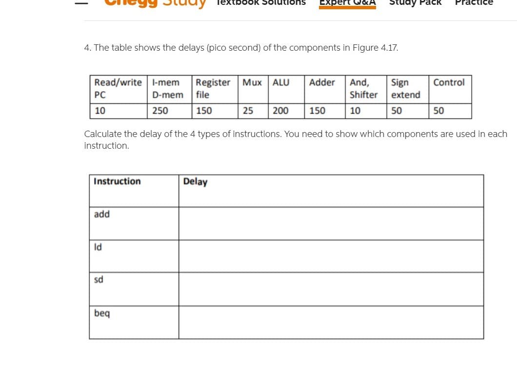
4. The table shows the delays (pico second) of the components in Figure 4.17.
Read/write l-mem
Adder
And,
Control
Register
file
Mux
ALU
Sign
PC
D-mem
Shifter
extend
10
250
150
25
200
150
10
50
50
Calculate the delay of the 4 types of instructions. You need to show which components are used in each
instruction.
Instruction
Delay
add
Id
sd
beq
![4.4 A Simple Implementation Scheme
257
Add
4
Add Sum
Shift
left 1
Branch
MemRead
MemtoReg
Instruction [6-0]
Control ALU0P
MemWrite
ALUSrc
RegWrite
Instruction [19-15]
Read
address
Read
register 1 Read
data 1
PC
Instruction [24-20]
Read
Zero
Instruction
register 2
[31-0]
ALU ALU
Read
Address data
Instruction [11-7]
Read
Write
register data 2
result
Instruction
memory
Write
data Registers
Data
Write
data memory
Instruction [31-0]
32
64
Imm
Gen
ALU
control
Instruction [30,14-12]
FIGURE 4.17 The simple datapath with the control unit. The input to the control unit is the 7-bit opcode field from the instruction.
The outputs of the control unit consist of two 1-bit signals that are used to control multiplexors (ALUSrc and MemtoReg), three signals for
controlling reads and writes in the register file and data memory (RegWrite, MemRead, and MemWrite), a 1-bit signal used in determining
whether to possibly branch (Branch), and a 2-bit control signal for the ALU (ALUOP). An AND gate is used to combine the branch control
signal and the Zero output from the ALU; the AND gate output controls the selection of the next PC. Notice that PCSrc is now a derived signal,
rather than one coming directly from the control unit. Thus, we drop the signal name in subsequent figures.](/v2/_next/image?url=https%3A%2F%2Fcontent.bartleby.com%2Fqna-images%2Fquestion%2F3c424593-3493-4336-8144-fffecfe46f12%2Ff458ac50-2078-4f3f-949c-50b10ef8d943%2F82an31q_processed.jpeg&w=3840&q=75)
Transcribed Image Text:4.4 A Simple Implementation Scheme
257
Add
4
Add Sum
Shift
left 1
Branch
MemRead
MemtoReg
Instruction [6-0]
Control ALU0P
MemWrite
ALUSrc
RegWrite
Instruction [19-15]
Read
address
Read
register 1 Read
data 1
PC
Instruction [24-20]
Read
Zero
Instruction
register 2
[31-0]
ALU ALU
Read
Address data
Instruction [11-7]
Read
Write
register data 2
result
Instruction
memory
Write
data Registers
Data
Write
data memory
Instruction [31-0]
32
64
Imm
Gen
ALU
control
Instruction [30,14-12]
FIGURE 4.17 The simple datapath with the control unit. The input to the control unit is the 7-bit opcode field from the instruction.
The outputs of the control unit consist of two 1-bit signals that are used to control multiplexors (ALUSrc and MemtoReg), three signals for
controlling reads and writes in the register file and data memory (RegWrite, MemRead, and MemWrite), a 1-bit signal used in determining
whether to possibly branch (Branch), and a 2-bit control signal for the ALU (ALUOP). An AND gate is used to combine the branch control
signal and the Zero output from the ALU; the AND gate output controls the selection of the next PC. Notice that PCSrc is now a derived signal,
rather than one coming directly from the control unit. Thus, we drop the signal name in subsequent figures.
Expert Solution
This question has been solved!
Explore an expertly crafted, step-by-step solution for a thorough understanding of key concepts.

Step by step
Solved in 2 steps

Knowledge Booster


Learn more about
Need a deep-dive on the concept behind this application? Look no further. Learn more about this topic, computer-science and related others by exploring similar questions and additional content below.Recommended textbooks for you
Database System Concepts
Computer Science
ISBN:
9780078022159
Author:
Abraham Silberschatz Professor, Henry F. Korth, S. Sudarshan
Publisher:
McGraw-Hill Education

Starting Out with Python (4th Edition)
Computer Science
ISBN:
9780134444321
Author:
Tony Gaddis
Publisher:
PEARSON

Digital Fundamentals (11th Edition)
Computer Science
ISBN:
9780132737968
Author:
Thomas L. Floyd
Publisher:
PEARSON
Database System Concepts
Computer Science
ISBN:
9780078022159
Author:
Abraham Silberschatz Professor, Henry F. Korth, S. Sudarshan
Publisher:
McGraw-Hill Education
Starting Out with Python (4th Edition)
Computer Science
ISBN:
9780134444321
Author:
Tony Gaddis
Publisher:
PEARSON
Digital Fundamentals (11th Edition)
Computer Science
ISBN:
9780132737968
Author:
Thomas L. Floyd
Publisher:
PEARSON

C How to Program (8th Edition)
Computer Science
ISBN:
9780133976892
Author:
Paul J. Deitel, Harvey Deitel
Publisher:
PEARSON

Database Systems: Design, Implementation, & Manag…
Computer Science
ISBN:
9781337627900
Author:
Carlos Coronel, Steven Morris
Publisher:
Cengage Learning

Programmable Logic Controllers
Computer Science
ISBN:
9780073373843
Author:
Frank D. Petruzella
Publisher:
McGraw-Hill Education