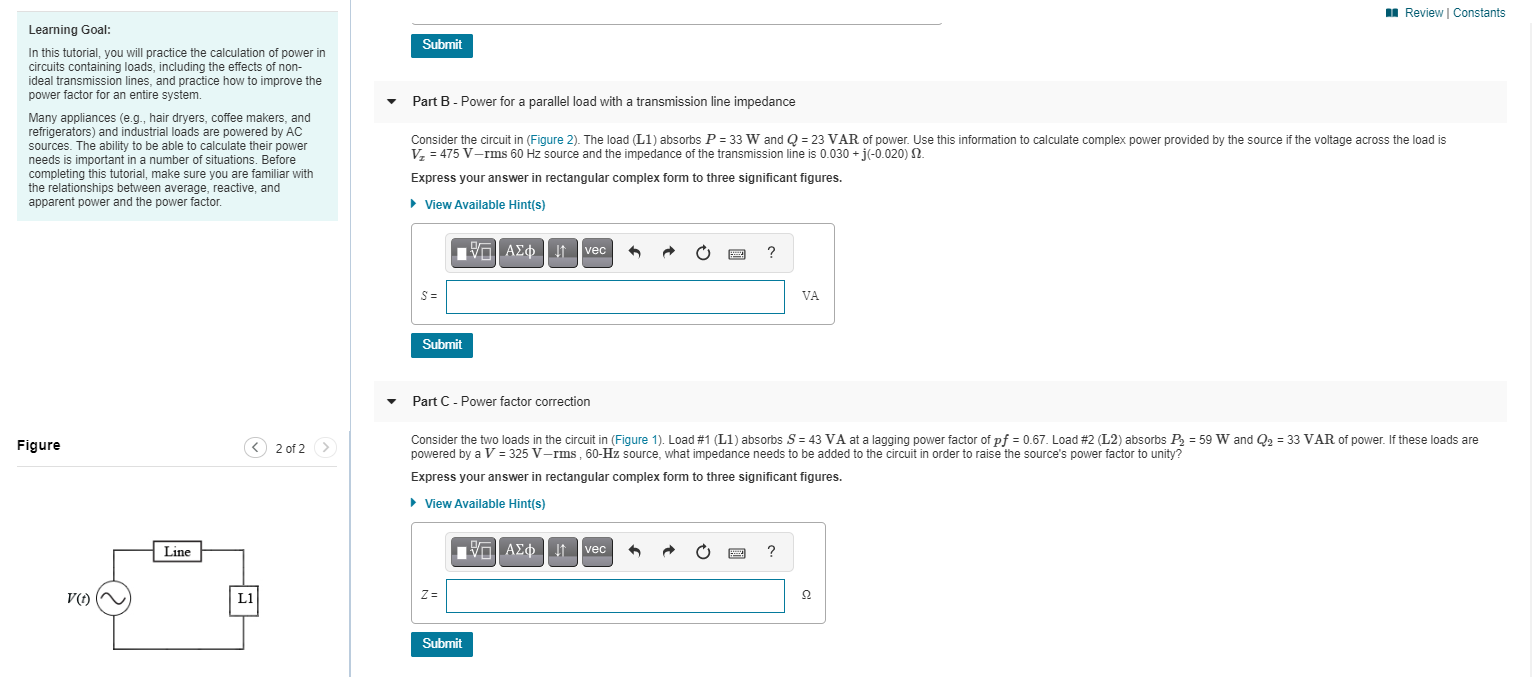
I Review | Constants Learning Goal: Submit In this tutorial, you will practice the calculation of power in circuits containing loads, including the effects of non- ideal transmission lines, and practice how to improve the power factor for an entire system. Part B - Power for a parallel load with a transmission line impedance Many appliances (e.g., hair dryers, coffee makers, and refrigerators) and industrial loads are powered by Ac sources. The ability to be able to calculate their power needs is important in a number of situations. Before completing this tutorial, make sure you are familiar with the relationships between average, reactive, and apparent power and the power factor. Consider the circuit in (Figure 2). The load (L1) absorbs P = 33 W and Q = 23 VAR of power. Use this information to calculate complex power provided by the source if the voltage across the load is V, = 475 V-rms 60 Hz source and the impedance of the transmission line is 0.030 + j(-0.020) 2. Express your answer in rectangular complex form to three significant figures. • View Available Hint(s) Va AEo !t vec ? S = VA Submit Part C - Power factor correction Figure Consider the two loads in the circuit in (Figure 1). Load #1 (L1) absorbs S = 43 VA at a lagging power factor of pf = 0.67. Load #2 (L2) absorbs P = 59 W and Q2 = 33 VAR of power. If these loads are powered by a V = 325 V–rms , 60-Hz source, what impedance needs to be added to the circuit in order to raise the source's power factor to unity? < 2 of 2 Express your answer in rectangular complex form to three significant figures. • View Available Hint(s) Line VG AED t vec ? V() L1 Z = Submit


Load flow analysis
Load flow analysis is a study or numerical calculation of the power flow of power in steady-state conditions in any electrical system. It is used to determine the flow of power (real and reactive), voltage, or current in a system under any load conditions.
Nodal Matrix
The nodal matrix or simply known as admittance matrix, generally in engineering term it is called Y Matrix or Y bus, since it involve matrices so it is also referred as a n into n order matrix that represents a power system with n number of buses. It shows the buses' nodal admittance in a power system. The Y matrix is rather sparse in actual systems with thousands of buses. In the power system the transmission cables connect each bus to only a few other buses. Also the important data that one needs for have a power flow study is the Y Matrix.
Types of Buses
A bus is a type of system of communication that transfers data between the components inside a computer or between two or more computers. With multiple hardware connections, the earlier buses were parallel electrical wires but the term "bus" is now used for any type of physical arrangement which provides the same type of logical functions similar to the parallel electrical bus. Both parallel and bit connections are used by modern buses. They can be wired either electrical parallel or daisy chain topology or are connected by hubs which are switched same as in the case of Universal Serial Bus or USB.


Trending now
This is a popular solution!

Step by step
Solved in 4 steps with 3 images


