igure 6 (a) shows the circuit diagram for a differential amplifier. You may assulne hat M, and Ma have identical parameters. Referring to Figure 6 (a): a) What kind of amplifier is it? What is its role in a three-stage op amp? b) Draw the small signal equivalent circuit and derive the differential voltage gain Adiy. For the analysis consider RDI Rp2= Rp. gml= gm2 gm. and ra ra2= r >>Rp State any assumption. c) What is the new Adir in the circuit of Figure 6 (b). where a PMOS current source has replaced the two drain resistors Roi has replaced the source resistor Rs? = Rp2= RD and a NMOS current sink
igure 6 (a) shows the circuit diagram for a differential amplifier. You may assulne hat M, and Ma have identical parameters. Referring to Figure 6 (a): a) What kind of amplifier is it? What is its role in a three-stage op amp? b) Draw the small signal equivalent circuit and derive the differential voltage gain Adiy. For the analysis consider RDI Rp2= Rp. gml= gm2 gm. and ra ra2= r >>Rp State any assumption. c) What is the new Adir in the circuit of Figure 6 (b). where a PMOS current source has replaced the two drain resistors Roi has replaced the source resistor Rs? = Rp2= RD and a NMOS current sink

Introductory Circuit Analysis (13th Edition)
13th Edition
ISBN:9780133923605
Author:Robert L. Boylestad
Publisher:Robert L. Boylestad
Chapter1: Introduction
Section: Chapter Questions
Problem 1P: Visit your local library (at school or home) and describe the extent to which it provides literature...

Related questions

Question
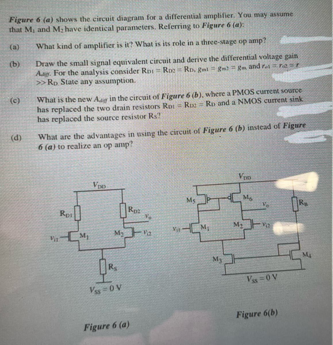
Transcribed Image Text:Figure 6 (a) shows the circuit diagram for a differential amphfier. You may assume
that M and M, have identical parameters. Referring to Figure 6 (a):
(a)
What kind of amplifier is it? What is its role in a three-stage op amp?
Draw the small signal equivalent eircuit and derive the differential voltage gain
Aag. For the analysis consider RDI RD2
>>Rp State any assumption.
(b)
RD. gml gm gm, and r re=r
What is the new Adr in the circuit of Figure 6 (b), where a PMOS current source
has replaced the two drain resistors Ror R Rp and a NMOS current sink
has replaced the source resistor Rs?
(c)
What are the advantages in using the circuit of Figure 6 (b) instead of Figure
6 (a) to realize an op amp?
(d)
Ven
Ms
Mg
Rp1
Rpa
Vo
HM,
My
M
Ma
M3
Vss 0 V
Vss 0 V
Figure 6(b)
Figure 6 (a)
Expert Solution
This question has been solved!
Explore an expertly crafted, step-by-step solution for a thorough understanding of key concepts.

Step by step
Solved in 2 steps with 1 images

Knowledge Booster


Learn more about
Need a deep-dive on the concept behind this application? Look no further. Learn more about this topic, electrical-engineering and related others by exploring similar questions and additional content below.Recommended textbooks for you
Introductory Circuit Analysis (13th Edition)
Electrical Engineering
ISBN:
9780133923605
Author:
Robert L. Boylestad
Publisher:
PEARSON

Delmar's Standard Textbook Of Electricity
Electrical Engineering
ISBN:
9781337900348
Author:
Stephen L. Herman
Publisher:
Cengage Learning

Programmable Logic Controllers
Electrical Engineering
ISBN:
9780073373843
Author:
Frank D. Petruzella
Publisher:
McGraw-Hill Education
Introductory Circuit Analysis (13th Edition)
Electrical Engineering
ISBN:
9780133923605
Author:
Robert L. Boylestad
Publisher:
PEARSON
Delmar's Standard Textbook Of Electricity
Electrical Engineering
ISBN:
9781337900348
Author:
Stephen L. Herman
Publisher:
Cengage Learning
Programmable Logic Controllers
Electrical Engineering
ISBN:
9780073373843
Author:
Frank D. Petruzella
Publisher:
McGraw-Hill Education

Fundamentals of Electric Circuits
Electrical Engineering
ISBN:
9780078028229
Author:
Charles K Alexander, Matthew Sadiku
Publisher:
McGraw-Hill Education

Electric Circuits. (11th Edition)
Electrical Engineering
ISBN:
9780134746968
Author:
James W. Nilsson, Susan Riedel
Publisher:
PEARSON

Engineering Electromagnetics
Electrical Engineering
ISBN:
9780078028151
Author:
Hayt, William H. (william Hart), Jr, BUCK, John A.
Publisher:
Mcgraw-hill Education,