# Implement the following function using Op Amps: O E = 11 - 11 V2 + 10 d Vs dt (ii) F2 = 11Vy – 15 V2 + 10 d Vg dt (iii) Fo = 11 V4 – 11 Ydt %3D
# Implement the following function using Op Amps: O E = 11 - 11 V2 + 10 d Vs dt (ii) F2 = 11Vy – 15 V2 + 10 d Vg dt (iii) Fo = 11 V4 – 11 Ydt %3D

Delmar's Standard Textbook Of Electricity
7th Edition
ISBN:9781337900348
Author:Stephen L. Herman
Publisher:Stephen L. Herman
Chapter18: Resistive-inductive Parallel Circuits
Section: Chapter Questions
Problem 13PP: In an R-L parallel circuit, IT=1.25 amps, R=1.2k, and XL=1k. Find IR

Related questions
Question
Pls give solution all
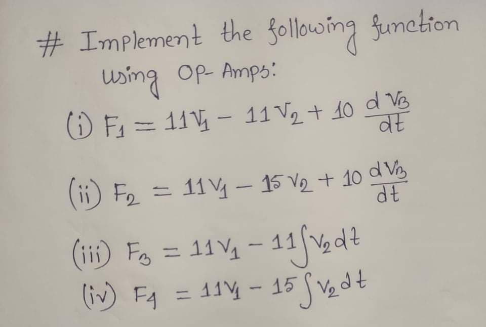
Transcribed Image Text:# Implement the following funetion
using Op Amps:
() F = 11 - 11 V2 + 10 d V
%3D
व
(ii) F2 = 11Vy- 15 V2 + 10 d Vy
( = 11 V4 - 11 gdt
(iii) Fo
(iv) FA:
= 11 - 15 V, dt
%3D
Expert Solution
This question has been solved!
Explore an expertly crafted, step-by-step solution for a thorough understanding of key concepts.

Step by step
Solved in 5 steps with 1 images

Recommended textbooks for you
Delmar's Standard Textbook Of Electricity
Electrical Engineering
ISBN:
9781337900348
Author:
Stephen L. Herman
Publisher:
Cengage Learning
Delmar's Standard Textbook Of Electricity
Electrical Engineering
ISBN:
9781337900348
Author:
Stephen L. Herman
Publisher:
Cengage Learning