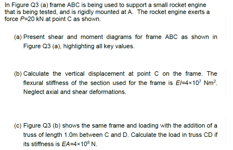
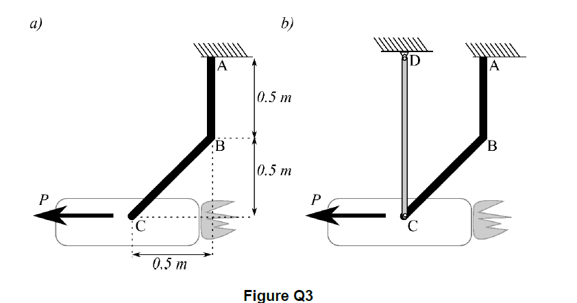
In Figure Q3 (a) frame ABC is being used to support a small rocket engine that is being tested, and is rigidly mounted at A. The rocket engine exerts a force P=20 kN at point C as shown. (a) Present shear and moment diagrams for frame ABC as shown in Figure Q3 (a), highlighting all key values. (b) Calculate the vertical displacement at point C on the frame. The flexural stiffness of the section used for the frame is El=4x10⁷ Nm². Neglect axial and shear deformations. (c) Figure Q3 (b) shows the same frame and loading with the addition of a truss of length 1.0m between C and D. Calculate the load in truss CD if its stiffness is EA=4×10⁸ N. b) a) D A A 0.5 m B 0.5 m P P 3: 0.5 т Figure Q3
In Figure Q3 (a) frame ABC is being used to support a small rocket engine that is being tested, and is rigidly mounted at A. The rocket engine exerts a force P=20 kN at point C as shown. (a) Present shear and moment diagrams for frame ABC as shown in Figure Q3 (a), highlighting all key values. (b) Calculate the vertical displacement at point C on the frame. The flexural stiffness of the section used for the frame is El=4x10⁷ Nm². Neglect axial and shear deformations. (c) Figure Q3 (b) shows the same frame and loading with the addition of a truss of length 1.0m between C and D. Calculate the load in truss CD if its stiffness is EA=4×10⁸ N. b) a) D A A 0.5 m B 0.5 m P P 3: 0.5 т Figure Q3

Chapter2: Loads On Structures
Section: Chapter Questions
Problem 1P

Related questions
Question
Transcribed Image Text:In Figure Q3 (a) frame ABC is being used to support a small rocket engine
that is being tested, and is rigidly mounted at A. The rocket engine exerts a
force P=20 kN at point C as shown.
(a) Present shear and moment diagrams for frame ABC as shown in
Figure Q3 (a), highlighting all key values.
(b) Calculate the vertical displacement at point C on the frame. The
flexural stiffness of the section used for the frame is El=4x10⁷ Nm².
Neglect axial and shear deformations.
(c) Figure Q3 (b) shows the same frame and loading with the addition of a
truss of length 1.0m between C and D. Calculate the load in truss CD if
its stiffness is EA=4×10⁸ N.
Transcribed Image Text:b)
a)
D
A
A
0.5 m
B
0.5 m
P
P
3:
0.5 т
Figure Q3
Expert Solution
This question has been solved!
Explore an expertly crafted, step-by-step solution for a thorough understanding of key concepts.

Step by step
Solved in 3 steps with 2 images

Recommended textbooks for you

Structural Analysis (10th Edition)
Civil Engineering
ISBN:
9780134610672
Author:
Russell C. Hibbeler
Publisher:
PEARSON

Principles of Foundation Engineering (MindTap Cou…
Civil Engineering
ISBN:
9781337705028
Author:
Braja M. Das, Nagaratnam Sivakugan
Publisher:
Cengage Learning
Structural Analysis (10th Edition)
Civil Engineering
ISBN:
9780134610672
Author:
Russell C. Hibbeler
Publisher:
PEARSON
Principles of Foundation Engineering (MindTap Cou…
Civil Engineering
ISBN:
9781337705028
Author:
Braja M. Das, Nagaratnam Sivakugan
Publisher:
Cengage Learning

Fundamentals of Structural Analysis
Civil Engineering
ISBN:
9780073398006
Author:
Kenneth M. Leet Emeritus, Chia-Ming Uang, Joel Lanning
Publisher:
McGraw-Hill Education


Traffic and Highway Engineering
Civil Engineering
ISBN:
9781305156241
Author:
Garber, Nicholas J.
Publisher:
Cengage Learning