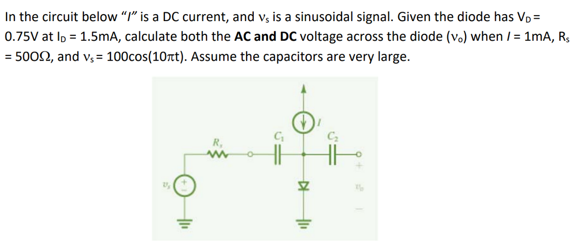
In the circuit below "I" is a DC current, and vs is a sinusoidal signal. Given the diode has V₁ = 0.75V at l = 1.5mA, calculate both the AC and DC voltage across the diode (v.) when / = 1mA, R₁ = 50022, and v₁ = 100cos(10лt). Assume the capacitors are very large. 21 +1₁ R, ▷ "
Q: A 2 Volt signal travels from 50 Ohms to 75 Ohms, find the voltage at the interface. If the 2…
A: The voltage at the interface is different in both cases:When going from 50 Ohms to 75 Ohms, the…
Q: Q1-50 kw ,250V, shunt DC generator has armature and field resistance of 0.02 2 and 50 2…
A:
Q: 2. A boost converter has an output of 30V from 12 V source input during the Continuous Conduction…
A: Given data: -Vo=30 VVin=12 VL=120 μHRL=50 Ωfs=25 kHzAs per the guidelines I can answer only first 3…
Q: Find the discrete-time signal having the following DTFT spectrum. (Hint: note the "frequency…
A: Given:DTFT of a DT signal,we need to find:discrete time signal corresponding to given DTFT.
Q: . " . Find these Vc (o): The voltage across the capacitor at Ic (0+): The current flowing inside the…
A:
Q: Use the tables of z-transform properties and pairs to find the z-transform for the following…
A:
Q: b. For the following Lissajous patterns find the Horizontal Frequency (Unknown frequency) if the…
A: The lissajous patterns are given by1.2.The vertical frequency, FV=50 Hz.We need to determine the…
Q: I ' I ' I I ' I I I I I ' I ' ' V1 -9 V R1 3kQ R3 M 5kQ 3 ww R2 10KQ '
A: Create the Circuit:Open Multisim and start a new schematic.From the component library, select…
Q: (c) Find the V, Q (Charge) and Energy of each capacitor and fill in the Table below. Determine the…
A: In the given circuit the value of the voltage across the capacitor, charge in the capacitor, energy…
Q: SUF 17. For the capacitive circuit shown below calculate the total capacitance CT on 20.3634 30 a-b…
A: The circuit diagram,
Q: Explain the steps and show the drawing, thank you
A: Given below solution Explanation:
Q: The function XCt) is Compressed in time by a Factor of two, then time-advanced for three seconds.…
A:
Q: Design the circuit (find values of L, R1, R2) so that the voltage is as shown in the figure. v(1) 8…
A: The given circuit isThe voltage, v(t) is given byWe need to determine the values of L, R1 and R2.
Q: Question 3 Plot the output voltage waveform for the analog switch. Analog input Control voltage…
A: The objective of the question is to plot the output voltage waveform for an analog switch given the…
Q: Why IG=0??! BJT Ic = BIB JFET ID = Inss(1 - V₁x) ² Vp ID = Is IG=0 A IC IE VBE 0.7 V
A:
Q: Analyse the circuit shown in Fig. 9 and draw the waveform at nodes v², v, and vo. Briefly explain…
A: In the given question we need to explain about the given Astable multivibrator circuit.
Q: #2-If the magnitude of an incident voltage wave on a load is 18 V and the magnitude of the incident…
A:
Q: A line charge of uniform density p₁ forms a semicircle of radius b in the upper half xy-plane.…
A: In this question we need to find the magnitude and direction of electric field intensity.
Q: Use Laplace transforms and node-voltage method to find vo (t) for t> 0 in the network. Assume zero…
A:
Q: 3. Suppose r0=0x20000000 and r1=0x12345678. All bytes in memory are initialized to 0x00. Suppose the…
A: Here's the table showing the memory values after the program has run: AddressData (Little…
Q: (a) Consider an upper SSB modulated wave Ac [m(t) cos(2nfet) - m(t) sin(2nfet)] and its Hilbert…
A: According to the question, the equation of the upper SSB modulated wave is given asThe Hilbert…
Q: The output voltage of an op amp is −4 V when the noninverting input is 1 mV. If the open-loop gain…
A: For the given opamp configuration the value of the inverting input needs to be calculated.
Q: H.W.(2) Determine the total conductance and resistance for the parallel network of Fig. shown below…
A: We need to determine the total conductance and resistance for the parallel network of Fig. shown…
Q: 4. Use the balanced-frequency method to estimate the frequency and duration of each state of the…
A: According to the question, from the time/year figure as shown belowWe need to calculate frequency…
Q: Q1) ↑+9V loks 10kЉ dal ww H|=> +5V }lokr :10 кЉ TITT Diode is ideal. Find I,V. Hint: Use Thevenin's…
A: The objective of the question is to find the current and voltage across the diode in a given circuit…
Q: Q 2) Find the Thevenin equivalent of the circuit at terminals a-b. 0.1io 40 92 + 10 Q2 20 Ω +501 b…
A: To calculate the value of VthRth of the given circuit
Q: 1. 2. 3. Express S₁ (t) and s₂ (t) in (a), (b), and (c) in terms of s(t), where A, 0 ≤t<T Otherwise…
A: The question is asking to express S₁ (t) and s₂ (t) in terms of s(t) and determine if the signal…
Q: Find the inverse Laplace transform of the equation below X(s): = 6 s² + 10+ 34
A: In the given questions we need to calculate the inverse laplace transform of the given function.
Q: the (A+B) (A+C) (B+C) = Y to its maxterm form using De Morgan's theorems and the four-step process.…
A: A maxterm, in the context of boolean algebra, is a term that represents the logical operation of an…
Q: Calculate the total resistance of a 500 feet of 3/8" Cu wire.
A: The material of the wire is copper.Length of the wire is feet m.Diameter of the wire is mm…
Q: How much electricity (kWh/yr) can this array provide in an average year? Round to the nearest 1,000…
A: Given that,
Q: Which of the following statements regarding the wind turbine gearbox are true? Select one or more: O…
A: Answer (a) After the gearbox the rotational speed of the shaft is slower than the rotational speed…
Q: 5) Error ep (%) h 1 1 a. Draw a plot of the controller output. 3 t(s) Proportional-Integral (PI)…
A: The objective of the question is to find the controller output for each time interval for a…
Q: Figure shows the LED display control circuit with switch S1. With the information given in the…
A: According to the question, for the given circuit as shown below3.1. Voltage VDS when the power of…
Q: α 8.00 V 12.0 V 2.00 Ω Μ Μ 6.00 Ω 4.00 Μ Ω Ω b
A: Given a circuit We need to find the current in the 2-ohm resistor(I2Ω) and the potential difference…
Q: Probет #3> A signal x (Z) = A shown is จ๊ก the The 3.0 Spectrum Х- - L. 1.5 cos canfit +8) безого…
A: Given:A cosine signal, we need to determine the spectrum of the signal.
Q: A three-phase load of 15 MW and 7 MVAr is connected to a 110-kV 60-Hz system. Find the current of…
A: In this question, we need to determine the current in the load. We know, Apparent power S= √3 VL
Q: Which of the following does the NEC recognize as a device? A) Light bulb B) Locknut C)…
A: The device recognised by NEC from the given set of elements needs to be identified.
Q: Given: • V₂ = 20 20° V f = 22 kHz . R = 390 02 L = 3.9 mH C = 20 nF (a) Find the resistance and net…
A:
Q: Apply source transformation to find v、 in the circuit.
A: In the given questions we need to calculate the voltage Vx by using the superposition theorem.
Q: 26. For the network in Fig. 6.88: Find the current 11. Calculate the power dissipated by the 4Q…
A: Resistance is a property of a material that describes its opposition to the flow of electric…
Q: Problem 6. Text Problem 2.3 (revised). Suppose for a certain FM system the demodulated SNR is 34 dB…
A: Given data: SNRdemod=34dBConvert SNR to linear scale: SNRdemod=103.4Recevier threshold is…
Q: 28. A circuit with four light-emitting diodes (LEDs) P, Q, R and S is shown below. Two LEDs are lit…
A: According to the question, we need to discuss the basic concept of LED on the operation of pn…
Q: Consider the circuit shown in Figure 6. SW1 is a "single pole single throw" (SPST) switch. (+1 R1…
A: given a circuit and asked find the voltage at A.
Q: Night has fallen and you’ve taken shelter in a room with 4 doors. You’ll need a good sleep so that…
A: Detailed answer shown belowExplanation: 1. Answering the questions:a) Minimum number of AA…
Q: For each of the following transfer function, S a. Find the values of and w b. Characterize the…
A: From the given second order systems transfer function the value of damping ratio, natural frequency…
Q: A battery with E= 4.30 V and no internal resistance supplies current to the circuit shown in the…
A: The given circuit isThe supply voltage is⇒ϵ=4.3 V.The supply voltage has zero internal…
Q: Draw the Thévenin and Norton equivalent circuits as seen by the terminals ab. Hint: this is a great…
A: Vth = 15 voltRth = 20 ohmi n = 0.75 AmpRn = 20 ohm Explanation:Step 1: Step 2: Step 3: Step 4:
Q: What is the overall capacitance between point A and B? A B O1F O2F O3F 4F C1 2 F C2 1 F C3 1 F
A:
Q: Make a capture of a two-bit down flip flop counter: first counter from 0 to 6 (jumping one) and…
A: Components:Two JK flip flops (Q1, Q0 and Q2, Q1) Clock signal NOT gates (2) AND gates (3) LEDs (4)…
The question is attached to jpeg picture of the circuit:
Trending now
This is a popular solution!
Step by step
Solved in 1 steps with 3 images
- What is the unit of measurement for the strength of a capacitor? microamp microtorque microfarad microwattWhat frequency must be applied to a 33-mH inductor to produce an inductive reactance of 99.526 ?You are a journeyman electrician working in an industrial plant. Your task is to connect an inductor to a 480-V, 60-Hz line. To determine the proper conductor and fuse size for this installation, you need to know the amount of current the inductor will draw from the line. The nameplate on the inductor indicates that it has an inductance of 0.1 H. An ohmmeter reveals that it has a wire resistance of 10 . How much current should this inductor draw when connected to the line?
- SPECS: For the following circuit, both sources are equal, they supply the input voltage Vin, withfunction Vin = 15 sin (ωt) V, a frequency of 60 Hz.These sources connect to a set of diodes that behave ideally as shown. in the figure. Both resistors R1 and R2 are 2.2 kΩ. CURCUIT: The output voltage VA (observe the pin from which it is measured) as a functionmathematical input voltage Vin. Plot the curves of Vin and VA on different graphs.Surface barrier diodes have a lower noise figure in high frequencies True False The capacitance of the Varactor diode increases with an increase in reverse bias voltage True False The dark current is a current that will exist with no applied illumination True False The lifetime of LCDs is longer than that of LEDs True False The liquid-crystal display (LCD) has the distinct advantage of having a lower power requirement than the LED (light emitting diodes) True FalseGiven the schematic below, assume D1 and D2 are silicon with forward voltages of 0.7V. Find the following (with solutions) a) Conditions required wherein none of the diodes are conducting b) If both diodes are not conduction, what is Vo? Express in terms of Vi c) Plot the overall relationship of Vo and Vi in the coordinate system shown below. Remember, you are to plot the transfer characteristics of the circuit.
- Consider a silicon P- N step junction diode with Nd = 1018 cm-3 and Na = 5 × 1015 cm-3 . Assume T=300K. Calculate the capacitance when it is under reverse biased at 1.5V. Assume a cross sectional area of 1um2. If you want to make the capacitance decrease by factor of 3 what should be the width of the depletion layer?For the attenuator circuit shown, assume C1 and C2 to be very large (∞) capacitors. Don’t be thrown off by the capacitors (How do they behave at DC? How do they behave at AC if C =∞). Assume D1 and D2 are identical diodes with n=1, V T = 25 mV (use the exponential model). a. Determine the value of the dc voltage, V_N when I = 1mA. b. Draw the small-signal equivalent circuit, replacing the diodes with their small signal resistive model, r_d. c. Determine the value of V_o/V_s when I = 1mA.A crystal diode having internal resistance rf, = 20ohm is used for half-wave rectification. lf the applied voltage v = 50 sin wt and load resistance RL, = 800ohms find: 1. I m, l dc and I rms 2. a.c. power input and dc power output 3. DC output voltage 4. Efficiency of rectification
- Given a diode current of 8 mA and n 1, find I s if the applied voltage is 0.5 V and the tem-perature is room temperature (25°C).The diode current in a p-n junction is modeled exponentially (given below.) When the p-n junction is polarized with 0.7V and 0.75V, the currents flowing through the diode are again measured on the basis of 1.36 mA and 7.20 mA. Accordingly, what is the ideality factor? (Note: Take the thermal voltage as mV)Since C = 47μF, RL = 1kW and Vs = 90 cos2000t in the given circuit, find the diode current in the one-time filling time range of the capacitanc