In the circuit below, the operational amplifier is ideal. If V₁ =10mV and V₂ = 50 mV, the output voltage (Vout) is
In the circuit below, the operational amplifier is ideal. If V₁ =10mV and V₂ = 50 mV, the output voltage (Vout) is

Delmar's Standard Textbook Of Electricity
7th Edition
ISBN:9781337900348
Author:Stephen L. Herman
Publisher:Stephen L. Herman
Chapter23: Resistive-inductive-capacitive Series Circuits
Section: Chapter Questions
Problem 4PP: This circuit is connected to a 1000-Hz line. The resistor has a voltage drop of 185 V. the inductor...

Related questions
Question
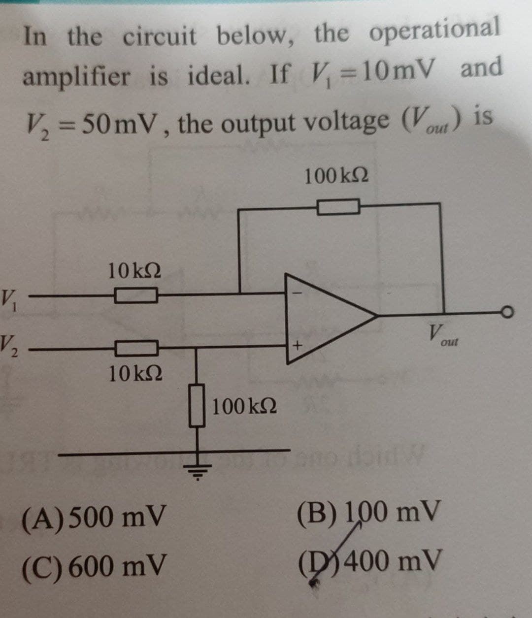
Transcribed Image Text:In the circuit below, the operational
amplifier is ideal. If V₁=10mV and
V₂ = 50 mV, the output voltage (Vout) is
100 ΚΩ
V₁
V₂
10 ΚΩ
10kQ
(A) 500 mV
(C) 600 mV
100 ΚΩ
V
out
(B) 100 mV
400 mV
(400
Expert Solution
This question has been solved!
Explore an expertly crafted, step-by-step solution for a thorough understanding of key concepts.

This is a popular solution!

Trending now
This is a popular solution!

Step by step
Solved in 2 steps with 1 images

Knowledge Booster


Learn more about
Need a deep-dive on the concept behind this application? Look no further. Learn more about this topic, electrical-engineering and related others by exploring similar questions and additional content below.Recommended textbooks for you
Delmar's Standard Textbook Of Electricity
Electrical Engineering
ISBN:
9781337900348
Author:
Stephen L. Herman
Publisher:
Cengage Learning
Delmar's Standard Textbook Of Electricity
Electrical Engineering
ISBN:
9781337900348
Author:
Stephen L. Herman
Publisher:
Cengage Learning