In the circuit given below with an input voltage of200 V. (need only handwritten solution .otherwise downvote.)
In the circuit given below with an input voltage of200 V. (need only handwritten solution .otherwise downvote.)

Power System Analysis and Design (MindTap Course List)
6th Edition
ISBN:9781305632134
Author:J. Duncan Glover, Thomas Overbye, Mulukutla S. Sarma
Publisher:J. Duncan Glover, Thomas Overbye, Mulukutla S. Sarma
Chapter3: Power Transformers
Section: Chapter Questions
Problem 3.28MCQ

Related questions
Question
In the circuit given below with an input voltage of200 V. (need only handwritten solution .otherwise downvote.)
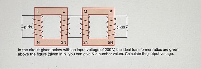
Transcribed Image Text:giriş.
P
çıkış
N
3N
2N
5N
In the circuit given below with an input voltage of 200 V, the ideal transformer ratios are given
above the figure (given in N, you can give N a number value). Calculate the output voltage.
Expert Solution
This question has been solved!
Explore an expertly crafted, step-by-step solution for a thorough understanding of key concepts.

Step by step
Solved in 3 steps with 2 images

Knowledge Booster


Learn more about
Need a deep-dive on the concept behind this application? Look no further. Learn more about this topic, electrical-engineering and related others by exploring similar questions and additional content below.Recommended textbooks for you
Power System Analysis and Design (MindTap Course …
Electrical Engineering
ISBN:
9781305632134
Author:
J. Duncan Glover, Thomas Overbye, Mulukutla S. Sarma
Publisher:
Cengage Learning
Power System Analysis and Design (MindTap Course …
Electrical Engineering
ISBN:
9781305632134
Author:
J. Duncan Glover, Thomas Overbye, Mulukutla S. Sarma
Publisher:
Cengage Learning