In the circuit of the figure below, the switch S has been open for a long time. It i then suddenly closed. Take & = 10.0 V, R₁ = 41.0 k2, R₂ = 175 k2, and C= 15.0- Let the switch be closed at t = 0. Determine the current in the switch when one- constant has elapsed. R₁ B R
In the circuit of the figure below, the switch S has been open for a long time. It i then suddenly closed. Take & = 10.0 V, R₁ = 41.0 k2, R₂ = 175 k2, and C= 15.0- Let the switch be closed at t = 0. Determine the current in the switch when one- constant has elapsed. R₁ B R

Delmar's Standard Textbook Of Electricity
7th Edition
ISBN:9781337900348
Author:Stephen L. Herman
Publisher:Stephen L. Herman
Chapter17: Resistive-inductive Series Circuits
Section: Chapter Questions
Problem 2PA: You are a journeyman electrician working in an industrial plant. Your task is to connect an inductor...

Related questions
Question
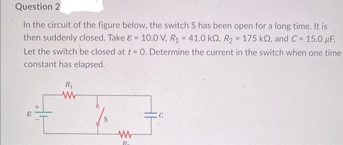
Transcribed Image Text:Question 2
In the circuit of the figure below, the switch S has been open for a long time. It is
then suddenly closed. Take & = 10.0 V, R₁ = 41.0 kQ2, R₂ = 175 kn, and C= 15.0 μF.
Let the switch be closed at t = 0. Determine the current in the switch when one time
constant has elapsed.
R₁
www
W
R
Expert Solution
This question has been solved!
Explore an expertly crafted, step-by-step solution for a thorough understanding of key concepts.

This is a popular solution!

Trending now
This is a popular solution!

Step by step
Solved in 2 steps with 2 images

Recommended textbooks for you
Delmar's Standard Textbook Of Electricity
Electrical Engineering
ISBN:
9781337900348
Author:
Stephen L. Herman
Publisher:
Cengage Learning
Delmar's Standard Textbook Of Electricity
Electrical Engineering
ISBN:
9781337900348
Author:
Stephen L. Herman
Publisher:
Cengage Learning