In the circuit of the given figure, assume that the diodes are ideal and the meter is an average indicating ammeter. The ammeter will read (a) 0.4 √2 A 0.8 (c) 7 A 02 Z 4 sincot volts 0₁ 10K (b) 0.4 A 0.4 (d) TC 10K
In the circuit of the given figure, assume that the diodes are ideal and the meter is an average indicating ammeter. The ammeter will read (a) 0.4 √2 A 0.8 (c) 7 A 02 Z 4 sincot volts 0₁ 10K (b) 0.4 A 0.4 (d) TC 10K

Delmar's Standard Textbook Of Electricity
7th Edition
ISBN:9781337900348
Author:Stephen L. Herman
Publisher:Stephen L. Herman
Chapter23: Resistive-inductive-capacitive Series Circuits
Section: Chapter Questions
Problem 3PP: The circuit is connected to a 60-Hz line. The apparent power in the circuit is 29.985 VA, and the...

Related questions
Question
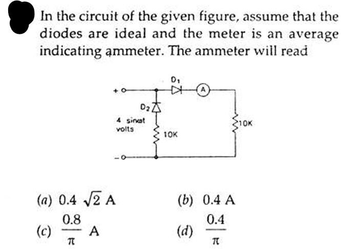
Transcribed Image Text:In the circuit of the given figure, assume that the
diodes are ideal and the meter is an average
indicating ammeter. The ammeter will read
(a) 0.4 √2 A
0.8
(c)
7
A
02 Z
4 sincot
volts
0₁
10K
(b) 0.4 A
0.4
(d)
TC
10K
Expert Solution
This question has been solved!
Explore an expertly crafted, step-by-step solution for a thorough understanding of key concepts.

Step by step
Solved in 2 steps with 2 images

Knowledge Booster


Learn more about
Need a deep-dive on the concept behind this application? Look no further. Learn more about this topic, electrical-engineering and related others by exploring similar questions and additional content below.Recommended textbooks for you
Delmar's Standard Textbook Of Electricity
Electrical Engineering
ISBN:
9781337900348
Author:
Stephen L. Herman
Publisher:
Cengage Learning
Delmar's Standard Textbook Of Electricity
Electrical Engineering
ISBN:
9781337900348
Author:
Stephen L. Herman
Publisher:
Cengage Learning