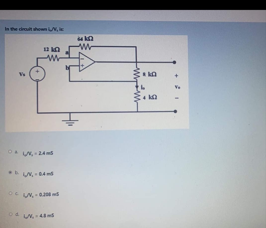
In the circuit shown i,N, is: 64 k2 12 k2 Vs 8 kn Vo 4 k2


Q: For the circuit shown, find R * and Vs В C wwm 3 Ω ¥1 A Y1 A F Vs A 1Ω D R = 4 Ohm Vs= 12 v %3D R =…
A:
Q: 2kQ 15V R, 24V 15mA UYE
A:
Q: For R1=4, R2=1, R3=8, V1=10 V, V2=44 V & L1=5 in the shown circuit, find the following: V2 vi(t LI t…
A:
Q: The network shown in Figure 2 contains two voltage sources, V, = 30 Z0° and V2 = 2020°. Using mesh…
A:
Q: Q2-For the circuit shown below, find value of ( R) then find the power (P) of resistance (R) 4A R…
A: The circuit can be made as:
Q: 1. Determine V1 in the circuit shown below. Vx + 10 kN 5 kN Vx 25 V V1 4
A: Given circuit,
Q: Use Kirchhoff's Law to find the power dissipated in the 50 resistor, determine the currents I,. I,,…
A: Given
Q: Q2) For the circuit shown, Find I, V, V, and the power dissipated in R.? E,+ 18V R sa E- -6 V Ry R4
A: First we will find current in all branches and than voltages using ohms law. power dissipated=V2R.
Q: For the circuit shown below, a) find the load resistance, RL, to obtain maximum power transfer in…
A: This question belongs to circuit theory . It is based on maximum power transfer theorem . For this…
Q: A is -30 V. Using Kirchhoff's laws, find (a) value of V and (b) power dissipated by 5 resistance. 3Ω…
A:
Q: For the circuit shown, find the current through the .(25 Ohm) resister. Using Thevenin Theorem 602…
A: The given circuit is, To determine the current through 25 Ω resistor i.e. I.
Q: Question 2 Find the value of RL for max power transfer to R1, in the circuit shown below, and…
A: Maximum power transfer theorem
Q: Use current and voltage division to find I1, I2, and V3 in the circuit shown if I = 4 mA, R1 =2.4kΩ,…
A: I = 4 m amp; R1 = 2.4 K ohm; R2 = 3.9 K ohm; R2 = 5.6 K ohm Find I1, Find I2,
Q: Q2)Solve the following problem In the network shown in figure below, find the value of RL such that…
A: In this question we need to find maximum power and load resistance for transfer maximum power to…
Q: R,=0.1 2 120 V { R, = 15 1
A: Circuit is given as,
Q: Use superposition to find the voltage Vọ in the circuit shown. 2 kn 2 k2 2 kn3 1 mA 6 V 2 mA 2 ko3…
A: Superposition theorem
Q: Determine practically the current through 10K2 in circuit below using Thevenin's theorem R2 1.2 kn…
A: In this question, we have to find out current through 10 kilo ohm using thevenin theorem...
Q: electrical network is shown in Figure A2, R, R 100 200 150 12V R Figure A2 e current through…
A: P
Q: Find Vb & Ve in the circuit shown. 100 Ix 15k 10 k a b Ix 1 V 2k
A: We will applly KCL at node b than we will get node voltage. Using node voltage we will find current…
Q: Find I, V1, V2, V3, and V4 in the circuit shown. V2 V, R2 R, 5 kN 3 Vác 3 kl 2 Vac V3 V31 9 Vác 4 kN…
A: I am attaching detailed solution image of this question.
Q: a) Find the power delivered by the dependent voltage source vsz. b) Find the power delivered by the…
A:
Q: Find the current flowing through the 20 Ohm resistor directly by simulating and verify the same…
A: I have solved this circuit first by using simple circuit reduction and current dividers and then…
Q: B in the network shown. 6 k2 A O 6 k2 2 k2 6 kQ AB Во- one: 18 K
A:
Q: 20 j2 n Vs +. ー10キ Vi Vo
A: The diagram is redrawn with current directions, Apply KVL to the left loop,…
Q: Q1) Determine the Norton equivalent circuit for the circuit shown: 5 k2 I kn 300 ma (1 7 kll 6 kfl…
A: “Since you have asked multiple questions, we will solve the first question for you. If youwant any…
Q: For the circuit shown below, a) find the load resistance, RL, to obtain maximum power transfer in…
A: The solution solution is given
Q: For the below circuit, determine the value of RLoad which results in the maximum power transfer, and…
A: Given: In the above given question they have mentioned an electrical circuit having independent…
Q: In the circuit shown, I = 4 mA. Find VS. 2 k2 5 k2 Vs 6 kQ 3 k2
A: The given circuit is as below: Taking the 5 kΩ & 3 kΩ in series:R=5+3 kΩR=8 kΩ
Q: For the circuit shown, find the Mesh currents. R1 R3 1Ω 2Ω R5 30 E 7 V V: 6 V R4 R2
A:
Q: 4. Use Thevenin's theorem to find the current flowing in the R1= 80 resistor for the circuit shown…
A:
Q: 1) Calculate IT, V1 & V2 in the circuit shown. R3 740 R4 16.4 0 R6 105 V V: 103.20 R1 36 0 R2 120 Vi…
A:
Q: For the circuit shown, find (a) R and (b) the power supplied by the 240 V source.
A: (a) The below circuit diagram shows all the currents and voltages.
Q: For the circuit shown, find the current through the .(25 Ohm) resister. Using Thevenin Theorem 602…
A: Solve as below
Q: 41. Consider the circuit shown below. (a) Find /, 1,, 1, 1µ, and /,. (b) Find the power supplied by…
A:
Q: In the circuit shown, he voltage across the resistor R, and R2 is 2.4V, and the voltage across the…
A:
Q: 4. Use Thevenin's theorem to find the current flowing in the R1= 8Q resistor for the circuit shown…
A: First we need to find the thevnin circuit then we can find current through RL = 8 ohm resistor.
Q: For the below circuit, find v, and v2. 90 Ω 60 Ω 150 23 750 3 V v v{ 30 N 40 2
A: Voltage division is used.
Q: In the network shown in Figure Q3(a), two independent voltage sources act on the elements in the…
A: We will apply KCL to find out current . First we will find out the current due to individual source…
Q: Determine the current through the resistor R1 in the circuit shown below using the mesh currents…
A:
Q: Find I, V1, V2, V3, and V4 in the circuit shown. V2 V83 V2 R2 R, 3 kn 2 Vde 5 kN 3 Vác R3 Vs1 9 Vdc…
A:
Q: 8) In the circuit below, solve for V1, V2 and i1. 10 2 20 2 2 A IA
A: Given circuit,
Q: Q3: Use the node-voltage method to find v in the circuit shown. 2.5N 10 i$150 100 2503 12 V 10n 2503…
A: Given, The circuit is
Q: For the circuit shown find V1, and V2. 2 A V2 V1 10 Ω 20 2 4 A
A: In the circuit, it can be seen that the voltage V2 is 0 Volt because it is directly connected to the…
Q: In the circuit shown, I 4 mA. Find VS. 2 k2 5 k2 Vs 6 k2 3 k2 Select one: O a. 4 O b. 38 O C. None…
A: In this question , we will find source voltage...
Q: Q1: Find the power of the 10-V voltage source? Is it supplying energy to the circuit or absorbing…
A:
Q: 3. For the circuit shown in the figure, find a) I in 20 2 b) V at 20 2 c) I in 75 N d) V at 75 N e)…
A:
Q: circuit given is R2 R3 V R1 A I2 = 4.5A
A:
Q: a) For the circuit shown, use the node-voltage method to find v1, v2, and i1. 4.1 b) How much power…
A:
Q: For the circuit shown in the figure below. Find the value of (W/L)2 (M2 size) so that l =29 uA.…
A:
Q: 2. Use KCL to obtain currents, il, i2, and i3 in the circuit shown. 12 mA 8 mA 13 12 9 mA
A: Given circuit shown

Step by step
Solved in 2 steps with 2 images


- R1=560Ω, R2=1000Ω, R3=470Ω, R4=2200Ω, R5=1000Ω V1 =12V and V2 = 5V Calculate every current in the given circuit by using the superposition principle. ( IR1C=?, IR2C=?, IR3C=?, IR4C=?, and IR5C=?)For R1=6000, R2=6000, R3=6000, R4=1000, I1=0.008, V1=12, in the circuit shown below,then what is the value of :?a and ib and Vc and idUsing the following values for the circuit in the figure, find what is required in the questions? For the circuit in the figure, find the ones requested in the questions by using the following values? VDD= 30 V, IDSS=8 mA, VP=-6V, R1=110 MΩ, R2=18 MΩ RD=1.9 kΩ, RS=9.12 kΩ VD=? VS=? VDS=?
- Using Kirchhoff's Rules, compute the current (mA) and voltage (V) values of the circuit if R1=2kΩ and R2=7kΩ.For the circuit in the figure, find the ones requested in the questions by using the following values? VDD= 30 V, IDSS=8 mA, VP=-6V, R1=110 MΩ, R2=18 MΩ RD=1.9 kΩ, RS=3,68 kΩ VD=VS=VDS=Arm resistances of Wheatstone bridge are,R₁ = 200 £2R₂ = 400 2R₁ = 500 SR₁ = 600Input is, E5V. Find the bridge output voltage.
- 1. Circuit Topology (Show solution) a. Simplify the circuit below such that there is only one voltage source and one equivalent resistor Rs in the circuit. Do not use source transformation. What is Rs? b. Simplify the circuit below such that there is only one current source I1 and one equivalent resistor Rp in the circuit. Do not use source transformation. What is Rp?Solve step by steo a) and b) please a) Determine Vs and Rs from a voltage source equivalent to a current source with Is = 500 mA and Rs = 600 Ω b) Determine Is and Rs of a current source equivalent to a voltage source with Vs = 13V and Rs = 10ΩWrite the KCL equations for the circuit shown Node b:Node c: Node g: Node f:
- Need help with this Question The D-MOSFET circuit shown in Figure Q1(b) has IDSS = 3 mA and VGS(off) =−8 V. Given the following:R1 = 50 kΩR2 = 150 kΩRD = 1 kΩRS = 2 kΩVDD = +10 VVSS = −10 VDetermine VGS, ID and VDS.Using the following values for the circuit in the figure, find what is required in the questions? For the circuit in the figure, find the ones requested in the questions by using the following values? VDD= 30 V, IDSS=8 mA, VP=-6V, R1=110 MΩ, R2=18 MΩ RD=1.9 kΩ, RS=9.12 kΩ VG=? VGS=? ID=? VD=? VS=? VDS=?Consider the circuit diagram below. Given I = 2.5 mA and Is = 1.25 mA: a) Find the currents Is2, I2, I3, I4 and Iz. State your conclusion as a table of values. b) What is the voltage drop across R7? c) If Vab = 2.75 V, what is the value of Rs?