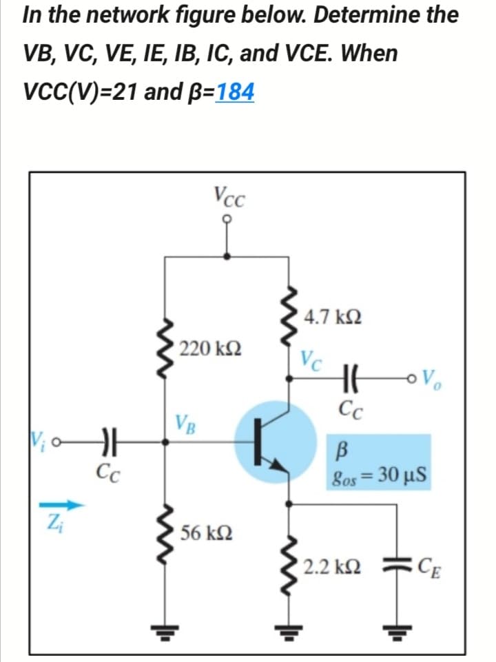
In the network figure below. Determine the VB, VC, VE, IE, IB, IC, and VCE. When vcC(V)=21 and B=184 Vcc 4.7 k2 220 k2 Vc Сс VB B 8os 30 μS %3D Cc 56 k2 2.2 k2 CE


Q: lectrical Engineering HVDC 4) A LCC HVDC project with capacity of 3000MW feeds into an AC system…
A: Given data: Capacity is given , Pdc=3000 MW Rated Voltage, V= 500 kV Short circuit current is given…
Q: För the deple =hown below, VTN = -2V and %3D (*) Kn = 0.1 Assume VDD = L v2 5V, Rs = 5 ko then the…
A:
Q: Vab = 100 cis 30° V and Vcb = 50 cis 120° V. Evaluate Vab - Vbc- O 111.8 cis -3.43° V 111.8 cis…
A:
Q: Uing Mesh analysis fina in fina Ban 202 40V E Aix
A: In this answer we will find the value of iA using the concept of mesh analysis as shown below.
Q: For circuit shown below, assuming VBE = 0.7 V. Determine: (а) Іво (b) Vв (c) Ico
A: Since we only answer up to 3 sub-parts, we’ll answer the first 3. Please resubmit the question and…
Q: 2. Determine I, V1, V2, and Vout using 2nd approximation. * 5kQ 3kQ V1 RL V2 3.3kQ 12 V Vout…
A: The solution is given below
Q: For the circuit below: (a) Determine the value of RL to which a maximum power can be delivered. (b)…
A: (a) Thevenin resistance across RL can be calculated as,
Q: I 8 s IL 2- For the circuit shown in figure, by using Kirchhoff's low's 12 equal to: lov 24v O i3 O…
A: Given circuit,
Q: 3.3 k2 C2 Ipss= 10 mA Ip=-6 V Z, 1 M2 I k2 For the given configuration the operating point is…
A: JFET(Junction field effect Transistor) is three terminal electronic device. Three terminal are…
Q: Q3\ For the circuit shown find: 1. By using voltage divider rule, calculate VR, Vc. 2. calculate…
A:
Q: RB RC 330k 1.2k R1 Q1 100k NPN VDD 20V J1 NJFET R2 RS 20k 2k
A: We need to find out current and voltage for given circuit.
Q: 3. Perform the following steps for the given circuit in below. RD= Rs= 1kQ, R1 = 300k2, R2 = 100k2,…
A:
Q: Q1) For the circuit shown in Figure below, apply nodal analysis to find Vx Vx 20 Q 2 A 10 Q. 0.2 Vx
A: In this answer let us find the value of voltage Vx using the nodal analysis as shown below.
Q: Determine: (a) Av2=Vcz/Vb2 (b) Av1=Vcj/Vb] (c) Vo if Vs=0.5mVp-p (d) Ais=Io/Is
A: Given the circuit, as shown below: We need to determine: a) Av2=Vc2Vb2 b) Av1=Vc1Vb1 c) Vo if…
Q: Q-2) For the network Vp = 12 V. Determine: a. Ip b. Vs and Vos c. Vg and Ves d. V. 18 V 2 kQ o V =…
A:
Q: 3. For the following figure, determine VDQ, VGSQ, VD and Vps. 14 V 1.2 k2 Ipss =6 mA Vp =-4 V 1 M2…
A: We need to find out current and voltage for given circuit
Q: For the network of the figure, determine: a. Is. -0+18 V b. Ic. c. VE. 9.1 ΚΩ d. VCE. 510 ΚΩΤ lc 510…
A: We need to find out current and voltage for given circuit
Q: %3D In the network below, the Voltage "Vo 0.5 V". Calculate R? R IR 4 5 - VR + 12 V 1, 21, Select…
A: This question belongs to circuit theory . It is based on the concept of kirchhoff's voltage law and…
Q: For the circuit shownin Figure IF Vec= 16V, Rc= 3-9kn Vcc RI= 39, R2=4.7ke Rc RI RE = 1.2 Ks2, B=100…
A:
Q: Q2: Find Avs for this circuit, hie=1kN and B=100. Vcc 47k 3.9k 500 Vs Vo 12knS 1.2k 1K
A:
Q: For the network in following figure, i) Identify the biasing configuration ii) Determine Ip,and V…
A:
Q: Q: For the network of figure below : a. Determine re. b. Calculate Zi and Zo. c. Find Av. Vcc = 16 V…
A: from the circuit B = 100 Re = 1.2 k R2 = 4.7k
Q: 6. Determine vo in the circuit below using any method. 20 Ω 30 Ω vo :4Ω 60 2 40 2 16 V +
A: In this question, Determine Vo in this circuit . Here 2 nodes are consist.
Q: For the network shown below find Vo 10 j2 n j2 0 'I t 24/0° V -j2 0 10
A:
Q: Q1: Determine Vcc for the network of figure if Ay= -160 B=120,then find Aj, Zo, Zi and Vo 3.3 kohm…
A:
Q: For the network below, VD = 9 V. Determine: ID. VS and VDS. VG and VGS. VP. 18 V 2 kN 750 k2 A6 = 1…
A: We need to find current and voltage for given circuit
Q: For the network in following figure, Determine V ps , VD , and Vs. 14 V Rp 1.2 k2 IDss = 6mA Vp =…
A: Given
Q: For the circuit of Figure below, if Rs = 2 k2, Rp = 3 k2, RG = 1 M2, VDp = 20 V, Ipss = 10 mA and…
A:
Q: In the circuit given below, R = 16 2. Using mesh analysis, find the value of la, ib, and ic. a↓ 30 V…
A: Given circuit,
Q: 1. For cach one of the circuits shown (a) Vas, and gm. (b) Zi, and Zo. . (c) A, = and Von +12V E0.S.…
A: Since you have asked multiple question, we will solve the first question for you. If youwant any…
Q: 18 V 2.2 ka Ipss =8 mA Vp = -8 V Vesa 0.39 k For the network of the figure, determine: (a) Ipo and…
A: In the Circuit, Find the drain current and gate to source voltage. We know drain current ID = IDSS…
Q: 01: Determine Vcc, Vc for the network of figure if Ay=-200, B=200,then find A, Zo and Vo. 2.2 KOBUF…
A: We have given the following circuit Determine VCC and VC and Ai, Z0, Zi and V0
Q: 16. If Req = 500 in the circuit below, find R. Roa 30 12 www 1022 6092 1252 1292 1202
A:
Q: In the circuit given below, assume Vcc=5V, VBE = 0.7V, R₁ = 10k, RB = 20k and ß = 50. How much is…
A: We need to find out emitter current for given circuit
Q: 2.14: For parallel RLC circuit with R=2KO, L=10mH and C=10NF. Find the value of Q, @o. B. 1, 02 and…
A: For parallel RLC circuit R= 2K ohm L=10mH C=10nF Voltage V= 10V Find the quality factor, Resonance…
Q: .4 (a) In Figure Q.4(a), determine Ve and Is using either nodal or mesh analysis. 12045° V V1 V2…
A: In the circuit, Find the voltage across the capacitor and current in the Voltage source 120∠45. We…
Q: 2. For the given network, determine (a) I (b) Ic (d) 6 (d) VCE 918 V 560 ΚΩ IB 13.9 ΚΩ -Vc=8V Ic +…
A:
Q: Determine the approximate value of Vps of the given circuit below. VDD 20V 2.1kQ Q1 V. V = - 4.5V…
A: In this question, We need to choose the correct options Determine the approximate value of VDS of…
Q: RB RC 330k 1.2k R1 Q1 NPN 100k VDD 20V J1 NJFET R2 RS 20k 2k
A: We need to find base voltage for given circuit.
Q: Vab = 100 cis 30° V and Vcb = 50 cis 120° V. Evaluate Vab - Vbc- 111.8 cis 56.57° V 111.8 cis…
A:
Q: For the circuit shown, using nodal analysis, the value of V1 is equal to. 0.52 + Vx - 2vo 0.1252 Vi…
A:
Q: - Eind the VD, ID and VR yoltage in the circuit below. + 10 V 0.5 kn Vg (a)
A:
Q: Using re model, compute for the AC characteristic of below circuit. (Av) 15 V 10 k2 45 k2 21 k2 10…
A:
Q: For the following circuit, which of the following equations are valid based on Kirchhoff's Voltage…
A:
Q: For the circuit shown below, find Vc if lg = 11 µA and B = 186. +16 V 3.6 kN RE Vc Ic IB 1.2 k2
A:
Q: Use nodal analysis to find v, in the circuit 10 cos 10³t V where: N = 6 (+1) ΝΩ ΝΩ io NμF HH Nio NmH…
A: Given circuit:- Where N=6 We have to find the value of vo by nodal analysis.
Q: For the circuit shown below: B = 100 and VBE = 0.7V, find: 1. VE Vc 3. VB Vcc 9V 1.0 k 22 k R 560 1…
A: To find VE, Vc, VB
Q: .For the given circuit, determine V1 and V2, and the output voltage Vout (5 2 k2 2 k2 Vi Va out 2V…
A: The given circuit is,
Q: Determine the approximate value of VD of the given circuit below. VDD 13.3 V 11.78 V 12.63 V 115M…
A:
Q: Q1/ Use Mesh analysis to find Ix in figure below, where Is= 4 cos(600t) A and Vs=110…
A:

Step by step
Solved in 3 steps with 3 images

- What is the output voltage for the circuit diagram given below? For VGS(on) = 4.5V , ID(on)=75mA , RDS(on) = 6ohmFor this question : https://www.bartleby.com/questions-and-answers/i-need-a-circuit-that-will-do-normal-am-modulation-using-diode-switching-and-then-demodulate-it-enve/b8317fe9-a8b5-4b96-8fb7-1fb978c62717 I used the circuit in the provided photo And i got wrong values, the output should be the message signal but i got another ouput. I provided a photo after the circuit photo that shows the result in the time domain.For the circuit in the figure, find the ones requested in the questions by using the following values? Vcc= 11 V, β=125, RF=227 kΩ, RC=3,6 kΩ, RE=0,9 kΩ IB=? IC=? IE=? VCE=? VCB=?
- (CLO-3, C3, C5 , C4)a. Draw a Thevenin equivalent circuit of the circuit shown in the figure below b. Drive the equation for emitter current IEc. Find the collector current Ic and VEC ?R1 = (010 + 25) kΩ R2 =15kΩRC = 3 kΩRE = 1.4 kΩβDC = 150 VEE = +12 VAre the following statements correct or wrong? Justify your answer. (a) GTO requires very high current applied to its gate to be turn ofr. (b) IGBT is a current driven device. (c) IGBT is more efficient than BJT in high power applications. (d) Thyristors are used only for low voltage, low current applications. (e) MOSFETS are used for low frequency applications.Are the following statements correct or wrong? Justify your answer. (a) GTO requires very low current applied to its gate to be turn off. (b) IGBT is a voltage driven device. (c) BJT is more efficient than IGBT in high power applications. (d) Thyristors are used only for low voltage, low current applications. (e) MOSFETs are used for high frequency applications.
- Calculate Ic, Vcc, β, and RB for the circuit shown belowCOURSE: INDUSTRIAL ELECTRONICS DEGREE: BS ELECTRICAL ENGINEERING For a unijunction transistor with VBB = 20V, n = 0.65, RB1 ✓ 2K-ohms (IE = 0), and VD = 0.7, determine: a) RB2 b) RBB c) VRB1 d) VPAre the following statements correct or wrong? Justify your answer.(a) GTO requires very high current applied to its gate to be turn off.(b) IGBT is a current driven device.(c) IGBT is more efficient than BJT in high power applications.(d) Thyristors are used only for low voltage, low current applications.(e) MOSFETs are used for low frequency applications. (I got the answer in the search but if possible,i want it in a slightly different way)
- For the circuit in the figure, find the ones requested in the questions by using the following values? Vcc= 23 V, β=66, RB=506 kΩ, RC=4,4 kΩ, RE=1,5 kΩ IE=? VCE=? VCB=?which terminal dose not belong to the SCRT? a-anode b-cathode c-base d-gateVLSI Wafer Yield Given the defect density D= and chip area A, use Murphy's yield model to estimate the chip yield. Calculate for D=0.5 defects/cm2 D=0.5 defects/cm2 and A=1.5 cm2 A=1.5 cm2.