In the structure shown, an 9-mm-diameter pin is used at 4, and 12-mm-diameter pins are used at B and D. Knowing that the ultimate shearing stress is 250 MPa at all connections and that the ultimate normal stress is 450 MPa in each of the two links joining B and D, determine the allowable load P if an overall factor of safety of 1.2 is desired. Assume link ABC to be rigid. Top view 330 All dimensions are in mm 390 22 B 20 T# 22 Front view D Side view P= kN X
In the structure shown, an 9-mm-diameter pin is used at 4, and 12-mm-diameter pins are used at B and D. Knowing that the ultimate shearing stress is 250 MPa at all connections and that the ultimate normal stress is 450 MPa in each of the two links joining B and D, determine the allowable load P if an overall factor of safety of 1.2 is desired. Assume link ABC to be rigid. Top view 330 All dimensions are in mm 390 22 B 20 T# 22 Front view D Side view P= kN X

Related questions
Question
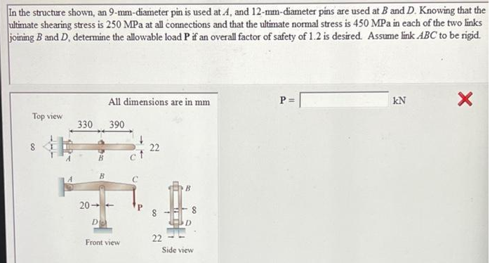
Transcribed Image Text:In the structure shown, an 9-mm-diameter pin is used at 4, and 12-mm-diameter pins are used at B and D. Knowing that the
ultimate shearing stress is 250 MPa at all connections and that the ultimate normal stress is 450 MPa in each of the two links
joining B and D, determine the allowable load P if an overall factor of safety of 1.2 is desired. Assume link ABC to be rigid.
Top view
330
B
All dimensions are in mm
D
390
20--
Front view
22
00
22
D
Side view
P =
kN
X
Expert Solution
This question has been solved!
Explore an expertly crafted, step-by-step solution for a thorough understanding of key concepts.

Step by step
Solved in 3 steps with 3 images
