Input A Input B Output F Input Input A'B'C 1 A'B'C 1 A'BC' 1 1 АВС 1 AB'C' 1 1 AB'C 1 1 АВС 1 1 1 ABC
Input A Input B Output F Input Input A'B'C 1 A'B'C 1 A'BC' 1 1 АВС 1 AB'C' 1 1 AB'C 1 1 АВС 1 1 1 ABC

Introductory Circuit Analysis (13th Edition)
13th Edition
ISBN:9780133923605
Author:Robert L. Boylestad
Publisher:Robert L. Boylestad
Chapter1: Introduction
Section: Chapter Questions
Problem 1P: Visit your local library (at school or home) and describe the extent to which it provides literature...

Related questions
Question
Implementation of Combinational Functions using various Logic Gates
Transcribed Image Text:BCS
Digital Logic Design
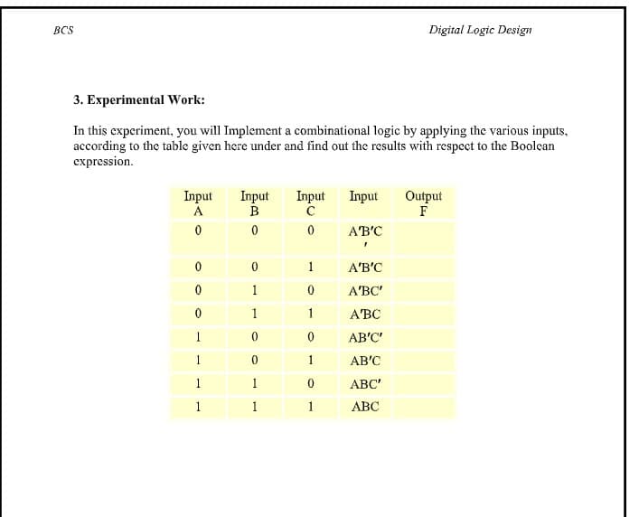
3. Experimental Work:
In this experiment, you will Implement a combinational logic by applying the various inputs,
according to the table given here under and find out the results with respect to the Boolcan
expression.
Input
A
Input
C
Input
Input
Output
F
A'B'C
1
A'B'C
1
A'BC'
1
1
АВС
1
AB'C'
1
AB'C
1
1
АВС"
1
1
1
АВС
Transcribed Image Text:BCS
Digital Logic Design
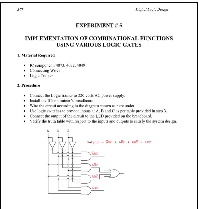
EXPERIMENT # 5
IMPLEMENTATION OF COMBINATIONAL FUNCTIONS
USING VARIOUS LOGIC GATES
1. Material Required
• IC component: 4073, 4072, 4049
• Connecting Wires
• Logic Trainer
2. Procedure
• Connect the Logic trainer to 220 volts AC power supply.
• Install the IC's on trainer's breadboard.
Wire the circuit according to the diagram shown as here under.
• Usc logic switches to provide inputs at A. B and C as per table provided in step 3.
• Connect the output of the circuit to the LED provided on the breadboard.
• Verify the truth table with respect to the inputs and outputs to satisfy the system design.
A
Out put
ABC + AEC + ABC + ABC
ABC
ABC
ABC
ABC
Expert Solution
This question has been solved!
Explore an expertly crafted, step-by-step solution for a thorough understanding of key concepts.

Step by step
Solved in 2 steps

Knowledge Booster


Learn more about
Need a deep-dive on the concept behind this application? Look no further. Learn more about this topic, electrical-engineering and related others by exploring similar questions and additional content below.Recommended textbooks for you
Introductory Circuit Analysis (13th Edition)
Electrical Engineering
ISBN:
9780133923605
Author:
Robert L. Boylestad
Publisher:
PEARSON

Delmar's Standard Textbook Of Electricity
Electrical Engineering
ISBN:
9781337900348
Author:
Stephen L. Herman
Publisher:
Cengage Learning

Programmable Logic Controllers
Electrical Engineering
ISBN:
9780073373843
Author:
Frank D. Petruzella
Publisher:
McGraw-Hill Education
Introductory Circuit Analysis (13th Edition)
Electrical Engineering
ISBN:
9780133923605
Author:
Robert L. Boylestad
Publisher:
PEARSON
Delmar's Standard Textbook Of Electricity
Electrical Engineering
ISBN:
9781337900348
Author:
Stephen L. Herman
Publisher:
Cengage Learning
Programmable Logic Controllers
Electrical Engineering
ISBN:
9780073373843
Author:
Frank D. Petruzella
Publisher:
McGraw-Hill Education

Fundamentals of Electric Circuits
Electrical Engineering
ISBN:
9780078028229
Author:
Charles K Alexander, Matthew Sadiku
Publisher:
McGraw-Hill Education

Electric Circuits. (11th Edition)
Electrical Engineering
ISBN:
9780134746968
Author:
James W. Nilsson, Susan Riedel
Publisher:
PEARSON

Engineering Electromagnetics
Electrical Engineering
ISBN:
9780078028151
Author:
Hayt, William H. (william Hart), Jr, BUCK, John A.
Publisher:
Mcgraw-hill Education,