Instructions a. Show your designed circuit b. Show the Load voltages in phase a, b and c c. Show the reference and the carrier signals of PWM generator d. Show the pulses for S₁, S3, and Ss e. Determine the rms value of the output voltage and the output current at each phase.
Instructions a. Show your designed circuit b. Show the Load voltages in phase a, b and c c. Show the reference and the carrier signals of PWM generator d. Show the pulses for S₁, S3, and Ss e. Determine the rms value of the output voltage and the output current at each phase.

Introductory Circuit Analysis (13th Edition)
13th Edition
ISBN:9780133923605
Author:Robert L. Boylestad
Publisher:Robert L. Boylestad
Chapter1: Introduction
Section: Chapter Questions
Problem 1P: Visit your local library (at school or home) and describe the extent to which it provides literature...

Related questions

Question
100%
Simulation is NOT required.
Please show calculations please. Thank you.
Transcribed Image Text:PWM Three-Phase Inverters
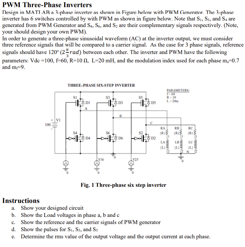
Design in MATLAB a 3-phase inverter as shown in Figure below with PWM Generator. The 3-phase
inverter has 6 switches controlled by with PWM as shown in figure below. Note that S₁, S3, and S4 are
generated from PWM Generator and S4, S6, and S₂ are their complementary signals respectively. (Note,
your should design your own PWM).
In order to generate a three-phase sinusoidal waveform (AC) at the inverter output, we must consider
three reference signals that will be compared to a carrier signal. As the case for 3 phase signals, reference
signals should have 120° (2 rad) between each other. The inverter and PWM have the following
parameters: Vdc =100, f-60, R=10, L-20 mH, and the modulation index used for each phase m₂=0.7
and m-9.
Instructions
100
Ellll
THREE-PHASE SIX-STEP INVERTER
Ⓒ°
SI
क
DI
D4
V36
S3
B
D6
V25
DS
C
ដ
|
RA
(R)
eeeee m
PARAMETERS:
f=60
R-10
L-20m
Fig. 1 Three-phase six step inverter
RB
RC
(R) (R)
LA LB
"eeeee m
(4)
breeeee m
a. Show your designed circuit
b. Show the Load voltages in phase a, b and c
c. Show the reference and the carrier signals of PWM generator
d. Show the pulses for S1, S3, and S5
e. Determine the rms value of the output voltage and the output current at each phase.
Expert Solution
This question has been solved!
Explore an expertly crafted, step-by-step solution for a thorough understanding of key concepts.

Step by step
Solved in 6 steps with 1 images

Knowledge Booster


Learn more about
Need a deep-dive on the concept behind this application? Look no further. Learn more about this topic, electrical-engineering and related others by exploring similar questions and additional content below.Recommended textbooks for you
Introductory Circuit Analysis (13th Edition)
Electrical Engineering
ISBN:
9780133923605
Author:
Robert L. Boylestad
Publisher:
PEARSON

Delmar's Standard Textbook Of Electricity
Electrical Engineering
ISBN:
9781337900348
Author:
Stephen L. Herman
Publisher:
Cengage Learning

Programmable Logic Controllers
Electrical Engineering
ISBN:
9780073373843
Author:
Frank D. Petruzella
Publisher:
McGraw-Hill Education
Introductory Circuit Analysis (13th Edition)
Electrical Engineering
ISBN:
9780133923605
Author:
Robert L. Boylestad
Publisher:
PEARSON
Delmar's Standard Textbook Of Electricity
Electrical Engineering
ISBN:
9781337900348
Author:
Stephen L. Herman
Publisher:
Cengage Learning
Programmable Logic Controllers
Electrical Engineering
ISBN:
9780073373843
Author:
Frank D. Petruzella
Publisher:
McGraw-Hill Education

Fundamentals of Electric Circuits
Electrical Engineering
ISBN:
9780078028229
Author:
Charles K Alexander, Matthew Sadiku
Publisher:
McGraw-Hill Education

Electric Circuits. (11th Edition)
Electrical Engineering
ISBN:
9780134746968
Author:
James W. Nilsson, Susan Riedel
Publisher:
PEARSON

Engineering Electromagnetics
Electrical Engineering
ISBN:
9780078028151
Author:
Hayt, William H. (william Hart), Jr, BUCK, John A.
Publisher:
Mcgraw-hill Education,