(iv) Design Problem: Referring to the circuit of Figure 2.1a, a designer wishes to create three equal potential differences (i.e. Vab= Vbc= Ved) of 5V each from a source-voltage, E = 15V. The maximum source-current, I available from the E battery-source is 5mA, and so the designer must ensure the current value stays within this requirement, and not exceed. Using KVL concept, analyse and determine a set of values for I, R₁, R₂ and R3 the designer can use to meet the above design specifications. Use standard resistor values available in your lab kit in your design. Record the results of your design analysis in Table 2.2. E a R₁ 15V b R₂ Theory result C Figure 2.1a: KVL Series Circuit R3 Design values => R₁ = VE I (mA) MultiSIM result VE a I Vab R₁ b R₂ R3 ? R₂ = ? R3 = ab (Volts) be (Volts) Theory MultiSIM Theory MultiSIM result result result result Figure 2.1b: KVL Series Circuit showing Voltmeter & Ammeter connections Vbc ? ed (Volts) Theory result MultiSIM result Table 2.2: Theoretical and MultiSIM results of the re-designed Series Circuit in Figure 2.1
(iv) Design Problem: Referring to the circuit of Figure 2.1a, a designer wishes to create three equal potential differences (i.e. Vab= Vbc= Ved) of 5V each from a source-voltage, E = 15V. The maximum source-current, I available from the E battery-source is 5mA, and so the designer must ensure the current value stays within this requirement, and not exceed. Using KVL concept, analyse and determine a set of values for I, R₁, R₂ and R3 the designer can use to meet the above design specifications. Use standard resistor values available in your lab kit in your design. Record the results of your design analysis in Table 2.2. E a R₁ 15V b R₂ Theory result C Figure 2.1a: KVL Series Circuit R3 Design values => R₁ = VE I (mA) MultiSIM result VE a I Vab R₁ b R₂ R3 ? R₂ = ? R3 = ab (Volts) be (Volts) Theory MultiSIM Theory MultiSIM result result result result Figure 2.1b: KVL Series Circuit showing Voltmeter & Ammeter connections Vbc ? ed (Volts) Theory result MultiSIM result Table 2.2: Theoretical and MultiSIM results of the re-designed Series Circuit in Figure 2.1

Introductory Circuit Analysis (13th Edition)
13th Edition
ISBN:9780133923605
Author:Robert L. Boylestad
Publisher:Robert L. Boylestad
Chapter1: Introduction
Section: Chapter Questions
Problem 1P: Visit your local library (at school or home) and describe the extent to which it provides literature...

Related questions

Question
100%
A list of available resistor values had been provided as an image. Please include all calculations and steps, thank you!
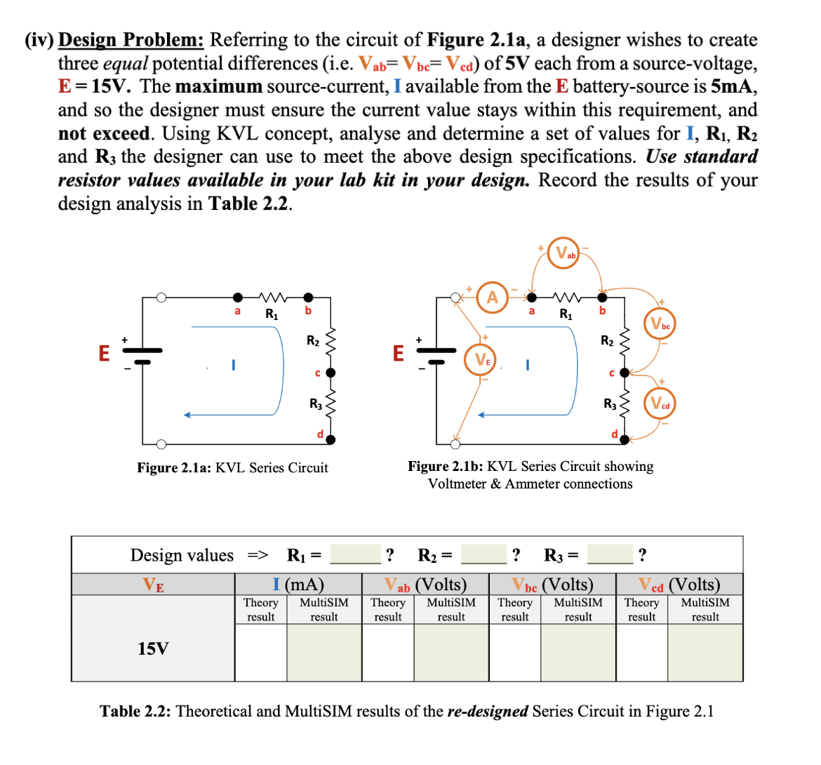
Transcribed Image Text:(iv) Design Problem: Referring to the circuit of Figure 2.1a, a designer wishes to create
three equal potential differences (i.e. Vab= Vbc=Vcd) of 5V each from a source-voltage,
E = 15V. The maximum source-current, I available from the E battery-source is 5mA,
and so the designer must ensure the current value stays within this requirement, and
not exceed. Using KVL concept, analyse and determine a set of values for I, R₁, R₂
and R3 the designer can use to meet the above design specifications. Use standard
resistor values available in your lab kit in your design. Record the results of your
design analysis in Table 2.2.
E
ww
a R₁
15V
b
R₂
Theory
result
с
Figure 2.1a: KVL Series Circuit
R3
Design values => R₁ =
VE
I (mA)
MultiSIM
result
?
R₂ =
ab (Volts)
Theory
result
VE
a
MultiSIM
result
I
Vab
R₁
? R3
b
=
R₂
Figure 2.1b: KVL Series Circuit showing
Voltmeter & Ammeter connections
C
be (Volts)
Theory MultiSIM
result
result
R3
Vbc
?
Ved (Volts)
Theory MultiSIM
result
result
Table 2.2: Theoretical and MultiSIM results of the re-designed Series Circuit in Figure 2.1
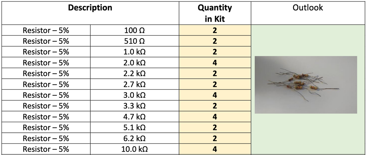
Transcribed Image Text:Description
Resistor - 5%
Resistor - 5%
Resistor 5%
Resistor 5%
Resistor - 5%
Resistor - 5%
Resistor - 5%
Resistor - 5%
Resistor - 5%
Resistor - 5%
Resistor - 5%
Resistor - 5%
100 Ω
510 Ω
1.0 kQ
2.0 ΚΩ
2.2 ΚΩ
2.7 ΚΩ
3.0 ΚΩ
3.3 ΚΩ
4.7 ΚΩ
5.1 ΚΩ
6.2 ΚΩ
10.0 ΚΩ
Quantity
in Kit
2
2
2
4
2
2
4
2
4
224
Outlook
Expert Solution
This question has been solved!
Explore an expertly crafted, step-by-step solution for a thorough understanding of key concepts.

Step by step
Solved in 3 steps with 3 images

Knowledge Booster


Learn more about
Need a deep-dive on the concept behind this application? Look no further. Learn more about this topic, electrical-engineering and related others by exploring similar questions and additional content below.Recommended textbooks for you
Introductory Circuit Analysis (13th Edition)
Electrical Engineering
ISBN:
9780133923605
Author:
Robert L. Boylestad
Publisher:
PEARSON

Delmar's Standard Textbook Of Electricity
Electrical Engineering
ISBN:
9781337900348
Author:
Stephen L. Herman
Publisher:
Cengage Learning

Programmable Logic Controllers
Electrical Engineering
ISBN:
9780073373843
Author:
Frank D. Petruzella
Publisher:
McGraw-Hill Education
Introductory Circuit Analysis (13th Edition)
Electrical Engineering
ISBN:
9780133923605
Author:
Robert L. Boylestad
Publisher:
PEARSON
Delmar's Standard Textbook Of Electricity
Electrical Engineering
ISBN:
9781337900348
Author:
Stephen L. Herman
Publisher:
Cengage Learning
Programmable Logic Controllers
Electrical Engineering
ISBN:
9780073373843
Author:
Frank D. Petruzella
Publisher:
McGraw-Hill Education

Fundamentals of Electric Circuits
Electrical Engineering
ISBN:
9780078028229
Author:
Charles K Alexander, Matthew Sadiku
Publisher:
McGraw-Hill Education

Electric Circuits. (11th Edition)
Electrical Engineering
ISBN:
9780134746968
Author:
James W. Nilsson, Susan Riedel
Publisher:
PEARSON

Engineering Electromagnetics
Electrical Engineering
ISBN:
9780078028151
Author:
Hayt, William H. (william Hart), Jr, BUCK, John A.
Publisher:
Mcgraw-hill Education,