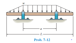
L- Prob. 7-12


Q: Calculate the moment (positive if counterclockwise, negative if clockwise) of the 370-N force on the…
A: Given data, Force = 370 N Theta (Θ) = 27° To find out the moment.
Q: 3. Determine the moment of the 50-N force (a) about point O and (b) about point C y, mm +C (0, 25) В…
A: To find moment about point O and C
Q: 4. Determine the distance 'a' as a fraction of the beam's length 'L' for locating the roller support…
A:
Q: 0.8 k 0.8 k 1.2 k -4 ft- B 8 ft 0.2 k /ft
A:
Q: The shaft is supported by a smooth thrust bearing at A and a smooth journal bearing at B. Draw the…
A: a) Consider the equilibrium of forces in vertical direction.
Q: *6-4. Draw the shear and moment diagrams for the canti- 2 kN/m lever beam. 6 kN-m 2 m
A:
Q: 4-47. Draw the shear and moment diagrams for cach member of the frame. 4 kN 4 kN 200 N/m 4 m 300 N/m…
A: Consider the free body diagram as;
Q: 10-13. When the 15 kN/m load is applied to the three- member frame the support at D settles 10 mm.…
A: As per our guidelines we are supposed to answer only one question. Kindly repost the other questions…
Q: Draw the shear and moment diagram Show your solution (input the maximum moment of the frame…
A:
Q: The frame is made from pipe that is fixed connected. If it supports the loading shown, determine the…
A:
Q: Determine the internal moment in kip-ft at the distance 14 ft. from point A (it is the point between…
A:
Q: Determine the moment of each of the three forces about point A. F2 = 300 N F = 250 N 30 60° -2 m- -3…
A:
Q: What is the Maximum moment in kN-m. Given: w - 15, a 1, b-5, and c-3. w kN/m A D. -am b m cm
A:
Q: 11-7. Determine the moment at B, then draw the moment diagram for the beam. Assume the supports at A…
A: Given: A,C are pinned supports B is roller support Load on span AB = 40 KN Load o span BC = 20 KN…
Q: Draw the moment diagrams for the beam using the method of superposition. Consider the beam to be…
A:
Q: Determine the internal moment in kip-ft at the distance 14 ft. from point A (it is the point between…
A:
Q: The bar is supported by the spring and smooth collar that allows the spring to be always…
A: FBD of the given problem:
Q: 10-13. When the 15 kN/m load is applied to the three- member frame the support at D settles 10 mm.…
A: Given data:-
Q: Each cord can sustain a maximum tension of 20 lb.Determine the largest weight of the lamp that can…
A: Free body diagram:-
Q: Draw the shear and moment diagrams for the shaft. Thesupport at A is a journal bearing and at B it…
A: Consider the free body diagram of the beam shown below. Consider the equilibrium moment about point…
Q: The compound beam is fixed at A, pin connected at B, and supported by a roller at C. Draw the shear…
A: Free body diagram of the given beam:
Q: Compute the combined moment of the two 70-lb forces about (a) point O and (b) point A. The moment is…
A: To compute the combined moment of the given forces. Given, Force F = 70 lb Dimension a = 5.8 in…
Q: 600 N E. The compound beam is fixed at A, pin connected at B, and supported by a roller at C. Draw…
A: Given beam-
Q: Determine the maximum positive moment of the beam shown. 12KN/m 20KN Ab 6m 2m
A:
Q: .Om Om 2.0m B A 3.0m C D hinge 5kN/m
A: Degree of static indeterminacy, Ds = 3 C- R' -m' C = no. of cuts made to make tree-like structure R'…
Q: hat is the Maximum moment in kN-m. Given: w = , a = 3, b = 5, and c = 2. w kN/m B C4 cam bm cm-
A:
Q: 4. Determine the distance 'a' as a fraction of the beam's length 'L' for locating the roller support…
A: Given moment at B should be zero. I have considered the moment at B from right end side .
Q: *10-20. Determine the moments at B and D, then draw the moment diagram. Assume A and C are pinned…
A: As per our guidelines we are supposed to answer only one question. Kindly repost the other questions…
Q: -100 N/m N-m Im 120 A 2m 1B 4m के с Draw the shear and moment diagram R₂ E
A:
Q: What is the Maximum moment in kN-m. Given: W = 20, a = 2, b = 8. and P - 80. PAN a m b m R. R. PE
A:
Q: 12 kN/m 40 kN 50 kN A C B -2 m- 4m 4 in -2 m
A: A loaded beam is given and it has been asked to determine shear force and bending moment diagram.…
Q: 11-1. Determine the moments at A, B, and C and then draw the moment diagram. EI is constant. Assume…
A: Given data:
Q: 4 kN 2 kN 2 kN/m B A 3 m -1m
A:
Q: *4-72. Determine the magnitude of the couple forces F so that the resultant couple moment on the…
A: Given data Point loads Angles To determine Couple F
Q: Problem 9-3. Determine the deflection at the end B of the clamped (Fixed at A) A-36 steel strip. The…
A:
Q: Determine the equivalent force-couple system at the center O for each of the three cases of forces…
A: a) Consider the free body m of the square plate.
Q: The belt passing over the pulley is subjected toforces F1 and F2, each having a magnitude of 40 N.…
A: It is required to determine the equivalent resultant force.
Q: *11-12. Determine the moments acting at A and B. Assume A is fixed supported, B is a roller, and C…
A:
Q: Draw the moment diagrams for the beam using the method of superposition.
A: The Superimposed beam is as shown: ∑MA=0-80(24)×242-MA1=0MA1=-23040 lb-ft∑Fy=0Ay1-(80×24)=0Ay1=1920…
Q: 5. The 20-kg ball is supported by two cables AB and AC. It is subjected to a horizontal force F =…
A: Free body diagram :
Q: (3) The beam is subjected to an internal moment of M= 50 kN.m as shown. Determine the percentage of…
A:
Q: d) 1) Find the maximum shear 2) Find the maximum moment A W=78.7kn/m В 120 inches
A: As per bartleby policy i can answer only one question at a time. Please upload again other…
Q: *4-72. Determine the magnitude of the couple forces F so that the resultant couple moment on the…
A: Given:- A crank is given with forces acting on it The magnitude of the couple forces are:- F1 = 150…
Q: 12-10. Determine the moment at B, then draw the moment diagram for the beam. Assume the supports at…
A: Moment Distribution Method : Fixed End Moments, FAB = -wL212=-64212=-8 KNM FBA=wL212=64212=8 KNM…
Q: Draw the shear and moment diagrom of the ame shown A is a pin and Cis a roller, also pint Bis a…
A: Diagrams showing how shear force changes over the length of a beam are called shear force diagrams.…
Q: Determine the internal moment in kip-ft at the distance 14 ft. from point A (it is the point between…
A:
Q: Draw the shear and moment diagrams for the shaft, and determine its required diameter to the nearest…
A: Data given:σallow= 30 ksiτallow= 15 ksiSince the value of P is not provided in the question,…
Q: 11-10. Determine the moments at A and B, then draw the moment diagram for the beam. El is constant.…
A: Given data:
Q: What is the Maximum moment in kN-m. Given: W - 30, a = 2, b - 7, and P - 50. PkN a m W AN m b m R.
A:
Q: 15 kN 10 kN Draw the shear and moment diagrams for each member of the frame. The members are pin…
A:
Determine the distance a between the bearings in terms of the shaft’s length L so that the moment in the symmetric shaft is zero at its center.


Trending now
This is a popular solution!

Step by step
Solved in 2 steps with 1 images


- Higher Order L.D.E (D3+6D2+5D-12)y=0Rigid members ABC and DEF are joined bysteel (Es = 180 GPa) links BE and CF. The steellinks consist of rectangular plates with crosssectional dimensions 25x35-mm. Determine:a) the change in length of BE and CFb) the distance between pts. A and D after theloading is applied. Pts. A and D are 240mm apart prior to the applied loading.Design a purlin for a roof truss having the following data:Span of the truss = 6.0mSpacing of truss = 3m c/c.Inclination of roof = 30oSpacing of Purlin = 2m c/cWind pressure = 1.5 kN/m2Roof coverage= A.C Sheeting weighing 200 N/m2Provide a channel section Purlin.
- The bracket BCD is hinged at € and attached to a control cable | ! at B. For the loading shown, determine (a) the tension in the cable, (b) the reaction at C. a=0. 18m 20N 20N 8 c o I_.l_nm—l—um—-l 02¢mLight-grade channel is used as a purlin of a truss whose top chord is sloped at 15degrees from the horizontal. Properties of channel section: Sx = 6.19 x 10^4 mm^3 Sy = 1.38 x 10^4 mm^3 Simple Span = 6 m with one sagrod at L/2 Loads Roof Loads (applied at centroid of purlins) Dead Load = 0.95 kPa (including weight of purlin) Live Load = 1.2 kPa Allowable Stress: Fbx = Fby =110 MPa a. Determine the maximum spacing of purlins (m) due to dead load plus live load only. (Hint: Analyze in terms of s and DCR<= 1.0 )Light-grade channel is used as a purlin of a truss whose top chord is sloped at 15degrees from the horizontal. Properties of channel section: Sx = 6.19 x 10^4 mm^3 Sy = 1.38 x 10^4 mm^3 Simple Span = 6 m with one sagrod at L/2 Loads Roof Loads (applied at centroid of purlins) Dead Load = 0.95 kPa (including weight of purlin) Live Load = 1.2 kPa Allowable Stress: Fbx = Fby =110 MPa a. Determine the maximum spacing of purlins (m) due to dead load plus live load only. (Hint: Analyze in terms of s and DCR<= 1.0 ) please i need answer thank you