Let's Recall (Review) Directions: Read the situations carefully. Choose the letter that corresponds to your answer. 1. Figure 1 shows a schematic diagram of a complex circuit. A student constructed this circuit into a breadboard. Is the circuit built correctly? R3 1kOhm R5 22K Ohm R2 3.3k Ohm R4 10K Ohm R1 47kOhm Figure 1. Circuit 1 a. Yes, the constructed circuit matches the schematic diagram. b. No, the schematic diagram shows that Ra and Rs should be parallel, but in the breadboard they are not parallel. c. No, the resistors are connected to each other correctly, but the red (positive) and black (negative) wires are reversed in the power supply. d. No, the schematic diagram shows that R2 and R3 should be connected to the power supply's negative terminal, but in the photo only one of them is connected. 2. Figure 2 shows another schematic of a complex circuit. Is the circuit built in the breadboard properly assembled? 0 Otem Figure 2. Circuit 2 a. No, R5 is connected to several the schematic, but it is not connected to any resistors in the breadboard. b. No, the power supply's negative terminal is connected to R3 and R4 in the schematic, but not in the photo. resistors in
Let's Recall (Review) Directions: Read the situations carefully. Choose the letter that corresponds to your answer. 1. Figure 1 shows a schematic diagram of a complex circuit. A student constructed this circuit into a breadboard. Is the circuit built correctly? R3 1kOhm R5 22K Ohm R2 3.3k Ohm R4 10K Ohm R1 47kOhm Figure 1. Circuit 1 a. Yes, the constructed circuit matches the schematic diagram. b. No, the schematic diagram shows that Ra and Rs should be parallel, but in the breadboard they are not parallel. c. No, the resistors are connected to each other correctly, but the red (positive) and black (negative) wires are reversed in the power supply. d. No, the schematic diagram shows that R2 and R3 should be connected to the power supply's negative terminal, but in the photo only one of them is connected. 2. Figure 2 shows another schematic of a complex circuit. Is the circuit built in the breadboard properly assembled? 0 Otem Figure 2. Circuit 2 a. No, R5 is connected to several the schematic, but it is not connected to any resistors in the breadboard. b. No, the power supply's negative terminal is connected to R3 and R4 in the schematic, but not in the photo. resistors in

Introductory Circuit Analysis (13th Edition)
13th Edition
ISBN:9780133923605
Author:Robert L. Boylestad
Publisher:Robert L. Boylestad
Chapter1: Introduction
Section: Chapter Questions
Problem 1P: Visit your local library (at school or home) and describe the extent to which it provides literature...

Related questions

Question

Transcribed Image Text:c. No, R; is connected to R2 in the schematic, but not in the breadboard.
d. Yes, the constructed circuit matches the schematic diagram.
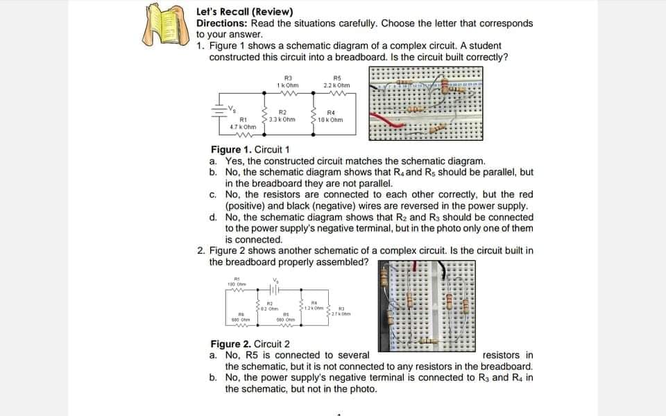
Transcribed Image Text:Let's Recall (Review)
Directions: Read the situations carefully. Choose the letter that corresponds
to your answer.
1. Figure 1 shows a schematic diagram of a complex circuit. A student
constructed this circuit into a breadboard. Is the circuit built correctly?
R3
Ik Ohm
R5
22K Ohm
R2
R4
10K Ohm
R1
4.7kOhm
3.3 k Ohm
Figure 1. Circuit 1
a. Yes, the constructed circuit matches the schematic diagram.
b. No, the schematic diagram shows that Ra and Rs should be parallel, but
in the breadboard they are not parallel.
c. No, the resistors are connected to each other correctly, but the red
(positive) and black (negative) wires are reversed in the power supply.
d. No, the schematic diagram shows that R2 and R3 should be connected
to the power supply's negative terminal, but in the photo only one of them
is connected.
2. Figure 2 shows another schematic of a complex circuit. Is the circuit built in
the breadboard properly assembled?
01 Ohm
Figure 2. Circuit 2
a. No, R5 is connected to several
the schematic, but it is not connected to any resistors in the breadboard.
b. No, the power supply's negative terminal is connected to R3 and R4 in
the schematic, but not in the photo.
resistors in
Expert Solution
This question has been solved!
Explore an expertly crafted, step-by-step solution for a thorough understanding of key concepts.

Step by step
Solved in 2 steps

Knowledge Booster


Learn more about
Need a deep-dive on the concept behind this application? Look no further. Learn more about this topic, electrical-engineering and related others by exploring similar questions and additional content below.Recommended textbooks for you
Introductory Circuit Analysis (13th Edition)
Electrical Engineering
ISBN:
9780133923605
Author:
Robert L. Boylestad
Publisher:
PEARSON

Delmar's Standard Textbook Of Electricity
Electrical Engineering
ISBN:
9781337900348
Author:
Stephen L. Herman
Publisher:
Cengage Learning

Programmable Logic Controllers
Electrical Engineering
ISBN:
9780073373843
Author:
Frank D. Petruzella
Publisher:
McGraw-Hill Education
Introductory Circuit Analysis (13th Edition)
Electrical Engineering
ISBN:
9780133923605
Author:
Robert L. Boylestad
Publisher:
PEARSON
Delmar's Standard Textbook Of Electricity
Electrical Engineering
ISBN:
9781337900348
Author:
Stephen L. Herman
Publisher:
Cengage Learning
Programmable Logic Controllers
Electrical Engineering
ISBN:
9780073373843
Author:
Frank D. Petruzella
Publisher:
McGraw-Hill Education

Fundamentals of Electric Circuits
Electrical Engineering
ISBN:
9780078028229
Author:
Charles K Alexander, Matthew Sadiku
Publisher:
McGraw-Hill Education

Electric Circuits. (11th Edition)
Electrical Engineering
ISBN:
9780134746968
Author:
James W. Nilsson, Susan Riedel
Publisher:
PEARSON

Engineering Electromagnetics
Electrical Engineering
ISBN:
9780078028151
Author:
Hayt, William H. (william Hart), Jr, BUCK, John A.
Publisher:
Mcgraw-hill Education,