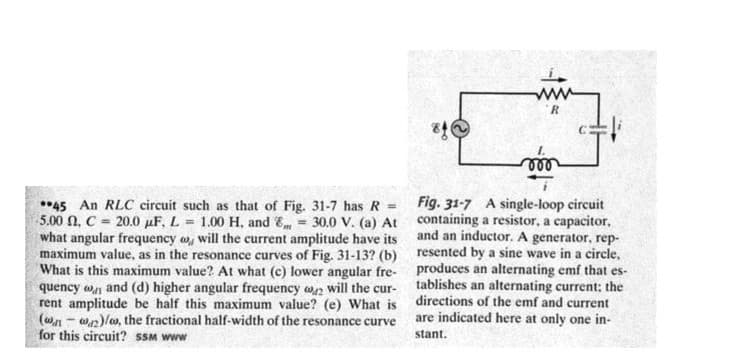
- 45 An RLC circuit such as that of Fig. 31-7 has R = 5.00 2. C 20.0 μF, L = 1.00 H. and 8, 30.0 V. (a) At what angular frequency o will the current amplitude have its maximum value, as in the resonance curves of Fig. 31-13? (b) What is this maximum value? At what (c) lower angular fre- quency and (d) higher angular frequency 2 will the cur- rent amplitude be half this maximum value? (e) What is (ww2)/0, the fractional half-width of the resonance curve for this circuit? SSM www 84 www R voo Fig. 31-7 A single-loop circuit containing a resistor, a capacitor, and an inductor. A generator, rep- resented by a sine wave in a circle. produces an alternating emf that es- tablishes an alternating current; the directions of the emf and current are indicated here at only one in- stant.
- 45 An RLC circuit such as that of Fig. 31-7 has R = 5.00 2. C 20.0 μF, L = 1.00 H. and 8, 30.0 V. (a) At what angular frequency o will the current amplitude have its maximum value, as in the resonance curves of Fig. 31-13? (b) What is this maximum value? At what (c) lower angular fre- quency and (d) higher angular frequency 2 will the cur- rent amplitude be half this maximum value? (e) What is (ww2)/0, the fractional half-width of the resonance curve for this circuit? SSM www 84 www R voo Fig. 31-7 A single-loop circuit containing a resistor, a capacitor, and an inductor. A generator, rep- resented by a sine wave in a circle. produces an alternating emf that es- tablishes an alternating current; the directions of the emf and current are indicated here at only one in- stant.

Related questions
Question
Transcribed Image Text:R.
ll
*45 An RLC circuit such as that of Fig. 31-7 has R = Fig. 31-7 A single-loop circuit
5.00 N, C = 20.0 µF, L = 1.00 H, and E = 30.0 V. (a) At containing a resistor, a capacitor,
what angular frequency w, will the current amplitude have its
maximum value, as in the resonance curves of Fig. 31-13? (b) resented by a sine wave in a circle,
What is this maximum value? At what (c) lower angular fre- produces an alternating emf that es-
quency w and (d) higher angular frequency wn will the cur-
rent amplitude be half this maximum value? (e) What is directions of the emf and current
(wn - wn)lw, the fractional half-width of the resonance curve
for this circuit? SSM www
and an inductor. A generator, rep-
tablishes an alternating current: the
are indicated here at only one in-
stant.
Transcribed Image Text:R=10 2
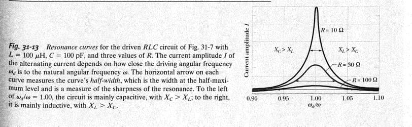
Fig. 31-13 Resonance curves for the driven RLC circuit of Fig. 31-7 with
L = 100 µH, C = 100 pF, and three values of R. The current amplitude I of
the alternating current depends on how close the driving angular frequency
w, is to the natural angular frequency w. The horizontal arrow on each
curve measures the curve's half-width, which is the width at the half-maxi-
mum level and is a measure of the sharpness of the resonance. To the left
of walw = 1.00, the circuit is mainly capacitive, with Xc > X; to the right,
it is mainly inductive, with X > Xc.
Xe > X,
X > Xc
R= 30 2
R= 1002
0.90
0.95
1.00
1.05
1.10
Current amplitude /
Expert Solution
This question has been solved!
Explore an expertly crafted, step-by-step solution for a thorough understanding of key concepts.

Step by step
Solved in 5 steps
