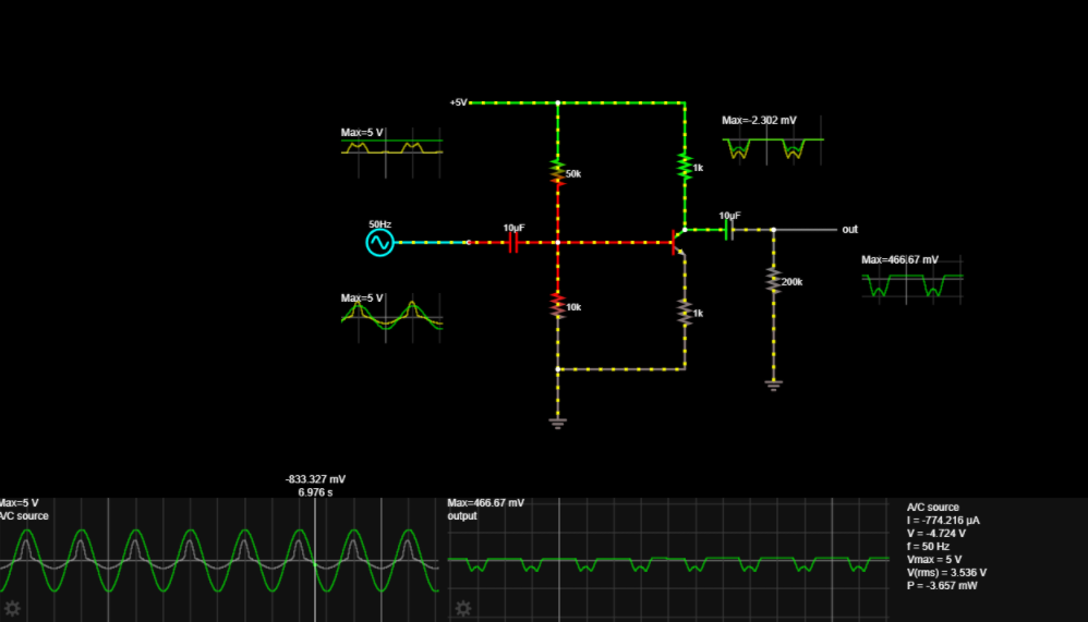
Max=2302 mv Max-5 V SOHE 10uF out (2) Max-466,67 mV May-5 V 833 327 mv 6.976 s Max-466.67 mV A/C source |=-774.216 HA V = 4.724 V 1= 50 Hz output Vmax =5 V V(ms) = 3.536 V P=-3.657 mW


Q: Eхample: For the circuit shown in Figure below find%3; a) The value of R for maximum power transfer.…
A: The given circuit is,
Q: 20 Vo Q-11: Find vo using superposition: -4 V 20 20
A:
Q: Q/ Using Source transformation theory to find vo in the below circuit. ЗА 10 2 25 Ω 4A 40 N Vo 20 2…
A: A current source in parallel with resistance can be replaced by voltage source with series resistor…
Q: Practice problem: Find the Norton equivalent circuit for the circuit in Figure below. Answer: RN =3…
A: Norton's Theorem states that it is possible to simplify any linear circuit to an equivalent circuit…
Q: For the circuit shown in the figure, find the Norton equivalent with IN referenced positive toward…
A:
Q: Vab = 100 cis 30° V and Vcb = 50 cis 120° V. Evaluate Vab - Vbc- O 111.8 cis -3.43° V 111.8 cis…
A:
Q: By msing reperfed smsce conver som, fnd the value of 20
A:
Q: +V. DD MOSFET Parameters: -V K, = µ„CoxWIL = 0.2 mA/V² VTN= 1 V SS 2 = 0 I 5 ΚΩ Vi = 1 V Rin Em = 1…
A: A)Small signal modelling
Q: Consider the given circuit where V=75 V. 3Ω ww O a Vz 0.5v% 10Ω Determine the Norton equivalent…
A:
Q: In the given circuit below, what is the total current supplied by the source? 82 24V- 12A A 19.67…
A:
Q: Which of the following is correct? 6. + U2 2 iz iz + i4 1 3 U3 5 is U5 O v2 + V5 - V4 = V6 V6 -V1-…
A:
Q: 5. Find the input impedance at 20 krad/s for the circuit shown in Figure 5. 200 £2 3 mH oooo + 0.5 Ω…
A:
Q: Multi-Source Circuit Analysis 3 Consider the circuit shown with the following parameters: 1₁ = 6 A…
A: Given circuit, Where, I1=6 AI2=15 AR1=22 ΩR2=68 Ω
Q: 5. Find Vo for the circuit given below. 10K w 9 V 20K 10 V 30K 12 V 40K 100K 9+Vcc 8-Voc 6V 20K Ans…
A:
Q: 20V 2と2 しIp V8, VG Ipss = 5 MA Vos Vp = -5V Vs, Vc Ic + VCE iB-100 VE lIE 4,2 EL Window Windows'u
A:
Q: V, = I, = R, = 250 0 V, = I, : 0.2 A 100 v R, = V = I, = R, = 150 Q 2 V, = I, = R, =
A:
Q: 1) The voltage VCE with ß = 200 is i) ii) iii) + VBB 10 V 13.06 V 6.94 V 9.3 V RB www 47 ΚΩ Rc 330 Ω…
A: Given, Current gain, β=200
Q: 3. Calculate the output voltage Vo- 10Ω 50Ω 252 502 V, oM- 10Ω OVo 10Ω V2 4. Determine Vo- 52 (a) V…
A:
Q: 26) Determine the output voltage for the network of figure rd = 40 kn. Figure (5) Good Luck H '40 ΜΩ…
A: Given circuit is shown below. given that Vi=0.9mV, rd=40k
Q: Relate vo in the circuit below to vs. Vn R3 R2 Vo Vs Rs Vp, Vo Vn2 3RL R1
A:
Q: Vab = 100 cis 30° V and Vcb = 50 cis 120° V. Evaluate Vab - Vbc- O 111.8 cis -3.43° V 111.8 cis…
A:
Q: Sketch v, for the network of the figure below for the input shown. Show the details of your work. c1…
A: SOLUTION- During -ve half cycle of input, diode ON (forward biased) Vin = -120 V (-ve cycle)…
Q: Convert the Thevenin's equivalent circuit shown in the figure below to Norton's equivalent circuit.…
A:
Q: a) The input to the circuit shown in Figure below is v, = -0.20 V. (i) What is vo? (ii) Determine…
A:
Q: Q2: For the circuit shown in the figure beside,determine the resistor values (RE, Rc and Rg). Voc 20…
A:
Q: 2. Find the parameters of re, VB, VC, Zi and Av for the given circuit in below. +20V B = 180 6.8kQ…
A:
Q: Determine vo in the circuit (use superposition principle)
A: In this question we need to find a voltage Vo by using superposition principal.
Q: v+ = 2.5 V RE= 0.7 k2 R1 = 60 ΚΩ R = Rc= 40 KQ 1.6 kQ V=-2.5 V Figure 1 Given B = 100, VEC(sat) =…
A: We need to find out current and voltage for given bjt circuit .
Q: Which one does NOT represent a source transformation of the circuit below? 40 30 ww 20 A 50 120 V O…
A: (1) The first transformation is shown below,
Q: +20 V Re || R A, : Rc 12 KΩ R 150 k R 50 k hFE = 200 R2 20 k RE 2.2 k
A:
Q: (c) For the circuit given in Figure Q.1(c), Find the value of i(t) and vo(t) if i,(t) = 6 cos (10t +…
A:
Q: Consider the circuit shown in Figure 10 below. H AVout AVin R Figure 10 in terms of R, C and w. AVin…
A:
Q: Use source transformation method to find the value of vo 0.4 mH 20n ww 5 cos 10°r V 0.2 pF: 802
A:
Q: Convert the Thevenin's equivalent circuit shown in the figure below to Norton's equivalent circuit…
A: In this question their interest in the calculation of Norton equivalent values with the help of…
Q: Determine the approximate value of Vps of the given circuit below. VDD 20V 2.1kQ Q1 V. V = - 4.5V…
A: In this question, We need to choose the correct options Determine the approximate value of VDS of…
Q: 250 Q 50 V 150 Q 80 Q 100 Q 300 Q Io O 2 A 250 V 200 Q 120 Q using mesh analysis, determine current…
A:
Q: 20ΚΩ For the circuit below find V ref of . (741) comparator +16 V Vo 741 470 Ω A
A:
Q: Q5) by using mesh analysis, determine v, in the circuit below. 100 20Ω 30 V 15i 80 V 40 η. 30 Ω.
A:
Q: Calculate Vx in the circuit of figure using the method of source transformation 40 /139 50 20/-90" V…
A:
Q: Find Norton's Equivalent circuit of the following circuit. 80 a | 1 2A 50 12V b
A:
Q: Determine the Norton equivalent circuit between nodes a and b Note if Norton resistance cannot be…
A: Norton's equivalent circuit
Q: Determine the approximate value of VGS of the given circuit below. VDD 20V $2.1kQ Q1 V. V. = -4.5V…
A: The solution is given below
Q: Example 1. Analyze the following circuit to determine all node voltages and branch currents. Assume…
A:
Q: Find the current R using superposition theorem. Assume the internal impedences of the voltage…
A: Ans. Shown below
Q: Vab = 100 cis 30° V and Vcb = 50 cis 120° V. Evaluate Vab - Vbc- 111.8 cis -3.43° V 111.8 cis 56.57°…
A: Given: values of Vab and Vbc To find: Vab - Vbc = ? Convert into polar form for calculation .
Q: 20 ww 8 V 2 A 6 V Figure 4.14 For Practice Prob. 4.5.
A: Given circuit,
Q: Use cut-set analysis to obtain all branch currents and voltages. 20 + va is 320 N 1.7 va 50 V 9 is
A: By applying nodal analysis, Here, v△=50-V1i△=V1-V25
Q: In the following circuit : Vout=2.8 V R R1 +1 Vo W 22 kM 22 kM R2 +1.8 VoW 22 kN o VOUT Select one:…
A:
Q: Q: For circuit shown below, find rd then calculate Zi, Zo and Av. Where VDD=20 V, IDSS = 10 mA and…
A: First we will do dc analysis to find out transconductance then we will do ac analysis to find out…
Q: 50 V 20 Ω 60 Ω + - 20 Ω 40 Ω : 30 Ω Consider the following circuit, what is the maximum power that…
A: Maximum power is delivered when the load resistance is equal to resistance RL=RTh RTh can be…
pls describe this circuit and relationships of waveforms, outputs inputs etc

Step by step
Solved in 3 steps with 1 images

- a. Apply a voltage of 120V at 60Hz to an impedance Z = 50 + 50j Ω as shown. b. Determine the value of C to bring the FP to 1 c. Tabulate the current in the source for different values of C d. Determine when the PF is lagging or leading-The vertical component of the phasor quantity: 130∠22.62° is ____ units. -The equivalent impedance of a series combination of a 8-ohm resistor, a 8-ohm capacitor, and a 14-ohm inductor has an angle of ____ degrees. -A parallel combination of a 24-ohm resistor and a 32-ohm inductor will result to a total impedance of with horizontal component of ____ ohms. -The equivalent impedance of a series combination of a 8-ohm resistor, a 8-ohm capacitor, and a 14-ohm inductor has a magnitude of ____ ohms. -A series circuit of two pure elements has the following applied voltages and resulting currents of 282.843 sin (314.159t + 30°) volts and 7.071 sin (314.159t - 23.13°) amperes respectively. What is the magnitude of the current in polar form?Could you use Zeq (impedance to solve)
- The voltage source (a) consists of E = 50 V ∠20° and Z = 100 Ω ∠30°. If this voltage source is converted to a current source (b), what is the value of the parallel impedance element Z and the current source?Reply as soon as possible and clearly, do not use italics 1) For the circuit in Figure, what is the value of S1, S2, S3, S4 and ST? Response format: a complex number in rectangular format. 2) What is the power factor of the circuit? (Response format for power factor: a number real rounded to two decimal places) and What is the value of the impedance seen by the source? ( Response format for impedance: a Complex number in rectangular format.)Find the total current to the parallel circuit of L = 45 mH and C = 400 µF with an applied voltage of v = 110sin(100t) V. Also, what is the total impedance, and power factor of the circuit? Is the circuit inductive or capacitive?
- Find the total current, total impedance, phase angle and reactive power in the circuit in the attached image along with drawing the voltage phasor diagram. Vin10V, R1 2709.08ohm, R2 = 1761.351ohm, C 1 = 1.096µF, C2 1.038µF Please show working thanks a lot.(d) An RC series network is composed of a 4 ohm resistor connected to a 50 microfarad capacitor. The supply voltage is represented by v= 150 Sin200tCalculate:(i) Impedance (ii) Vc and VR (iii) Phase angle and phasor diagram NB: On the phasor diagram, show the following parameters: I, VR, VL and VStermining the impedance and current of the system, the voltage across the resistor, and the voltage across the inductor. Could you please forward the response as a print of a handwritten answer? I got these two answers earlier. Which of them would be correct Impedance Z= (1000 + j 90.836) ohm Current I= 0.219∠-5.19° A Voltage across resistor VR = 219.097∠-5.19° V Voltage across inductor VL = 165.195∠84.81° V Impedance will be Z= 1004.052 ∠ 5.12° Current will be i = 0.221 ∠ -5.19° A. Volatge across resistor will be VR = 211.9∠ -5.19° V Volatge across inductor will be VL = 165.12 ∠ 84.81°V
- Solve for the impedance. Use 60Hz as frequency of the AC voltage source. Need your eligible and easy to understand solution. ThanksA balanced load is connected in star across a 3 phasec415V 50Hz supply. The load consists of a coil of resistance 25 ohms and inducrance 0.5 henry in paeallel with a purw resistance of 28 ohms and a pure capaciror of 60microfarads capacitance ,in each branch. Calculate a. The line currents? Need full working and answer has to be 9.3A Formola for inductance XL= 2×3.142FL FORMOLA FOR CAPACITOR XC= 1/2×3.142×FCIf 3-phase transfomer configuration in figure in has the givens as listed below: E-line on high side = 480V, turns ration = 2:1/coil, resistance per load =10, efficienscy = 100%. E/coil on the high side is _____, E/coil on the low side is___, E-phase on the low side is____, E/resitor of the load is____,(a-480v, b-240v, c-120 d-69.28v) I/resitor on the load is____, I-line on the low side is___, I-phase on the low side is____, I/coil on the low side is____(a-2A b-4A c-6.93 d-12A), I-phase on the high side is____, I-line on the high side is____(a-1A b-1.73A c-2A d-4A), Va/phase of the load is____, 3-phase Va on the high side is____(a-120VA b-360VA c-480VA d-1440VA).