· Measured Values - 1. Connect the circuit diagram as shown in the figure below b 15Ω R 25 1 R2 12 V 18 V | 15 V 30Ω R3 20Ω R4 10Ω R5 a d 30Ω R. 50Ω R, 14 V Ru 15 N R10 8 V Ry
· Measured Values - 1. Connect the circuit diagram as shown in the figure below b 15Ω R 25 1 R2 12 V 18 V | 15 V 30Ω R3 20Ω R4 10Ω R5 a d 30Ω R. 50Ω R, 14 V Ru 15 N R10 8 V Ry

Delmar's Standard Textbook Of Electricity
7th Edition
ISBN:9781337900348
Author:Stephen L. Herman
Publisher:Stephen L. Herman
Chapter18: Resistive-inductive Parallel Circuits
Section: Chapter Questions
Problem 10PP: In an R-L parallel circuit, ET=240 volts, R=560, and XL=330. Find apparent power.

Related questions
Question
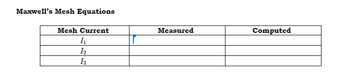
Transcribed Image Text:Maxwell's Mesh Equations
Mesh Current
Measured
Computed
I2
I3
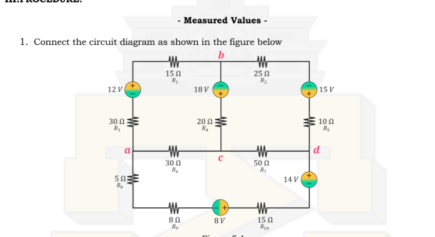
Transcribed Image Text:- Measured Values -
1. Connect the circuit diagram as shown in the figure below
b
25 N
R2
15 0
12 V
18 V
15 V
30 Ω
R3
20 Ω
R4
10 Ω
R5
a
|d
30 2
Ro
50 Ω
R,
50:
R
14 V
8Ω
Ro
15 Ω
R10
8 V
Expert Solution
This question has been solved!
Explore an expertly crafted, step-by-step solution for a thorough understanding of key concepts.

This is a popular solution!

Trending now
This is a popular solution!

Step by step
Solved in 2 steps with 1 images

Recommended textbooks for you
Delmar's Standard Textbook Of Electricity
Electrical Engineering
ISBN:
9781337900348
Author:
Stephen L. Herman
Publisher:
Cengage Learning
Delmar's Standard Textbook Of Electricity
Electrical Engineering
ISBN:
9781337900348
Author:
Stephen L. Herman
Publisher:
Cengage Learning