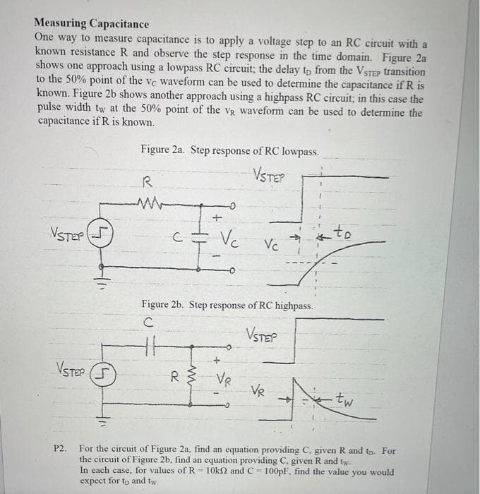
Measuring Capacitance One way to measure capacitance is to apply a voltage step to an RC circuit with a known resistance R and observe the step response in the time domain. Figure 2a shows one approach using a lowpass RC circuit; the delay tp from the VSTEP transition to the 50% point of the ve waveform can be used to determine the capacitance if R is known. Figure 2b shows another approach using a highpass RC circuit; in this case the pulse width tw at the 50% point of the vg waveform can be used to determine the capacitance if R is known. Figure 2a. Step response of RC lowpass.
Measuring Capacitance One way to measure capacitance is to apply a voltage step to an RC circuit with a known resistance R and observe the step response in the time domain. Figure 2a shows one approach using a lowpass RC circuit; the delay tp from the VSTEP transition to the 50% point of the ve waveform can be used to determine the capacitance if R is known. Figure 2b shows another approach using a highpass RC circuit; in this case the pulse width tw at the 50% point of the vg waveform can be used to determine the capacitance if R is known. Figure 2a. Step response of RC lowpass.

Delmar's Standard Textbook Of Electricity
7th Edition
ISBN:9781337900348
Author:Stephen L. Herman
Publisher:Stephen L. Herman
Chapter19: Capacitors
Section: Chapter Questions
Problem 2PA: You are an electrician working in an industrial plant. You discover that the problem with a certain...

Related questions
Question
please solve quickly.
Transcribed Image Text:Measuring Capacitance
One way to measure capacitance is to apply a voltage step to an RC circuit with a
known resistance R and observe the step response in the time domain. Figure 2a
shows one approach using a lowpass RC circuit; the delay tp from the VSTEP transition
to the 50% point of the ve waveform can be used to determine the capacitance if R is
known. Figure 2b shows another approach using a highpass RC circuit; in this case the
pulse width tw at the 50% point of the vg waveform can be used to determine the
capacitance if R is known.
Figure 2a. Step response of RC lowpass.
VSTEP
R
VSTEP
Vc
to
Vc
Figure 2b. Step response of RC highpass.
VSTEP
VSTEP
R
VR
VR
tw
For the circuit of Figure 2a, find an equation providing C. given R and tp. For
the circuit of Figure 2b, find an equation providing C, given R and tw.
In each case, for values of R- 10k2 and C = 100PF, find the value you would
expect for tp and tw.
P2.
!!
Expert Solution
This question has been solved!
Explore an expertly crafted, step-by-step solution for a thorough understanding of key concepts.

This is a popular solution!

Trending now
This is a popular solution!

Step by step
Solved in 6 steps

Recommended textbooks for you
Delmar's Standard Textbook Of Electricity
Electrical Engineering
ISBN:
9781337900348
Author:
Stephen L. Herman
Publisher:
Cengage Learning

Electricity for Refrigeration, Heating, and Air C…
Mechanical Engineering
ISBN:
9781337399128
Author:
Russell E. Smith
Publisher:
Cengage Learning
Delmar's Standard Textbook Of Electricity
Electrical Engineering
ISBN:
9781337900348
Author:
Stephen L. Herman
Publisher:
Cengage Learning
Electricity for Refrigeration, Heating, and Air C…
Mechanical Engineering
ISBN:
9781337399128
Author:
Russell E. Smith
Publisher:
Cengage Learning