method of heat transfer principle is used to monitor changes in temperature in non contact type temperature sensors.
method of heat transfer principle is used to monitor changes in temperature in non contact type temperature sensors.

Chapter19: Special-purpose Outlets-water Pump, Water Heater
Section19.2: Water Heater Branch Circuit
Problem 8R: For residential water heaters, the Consumer Product Safety Commission suggests a maximum temperature...

Related questions
Question
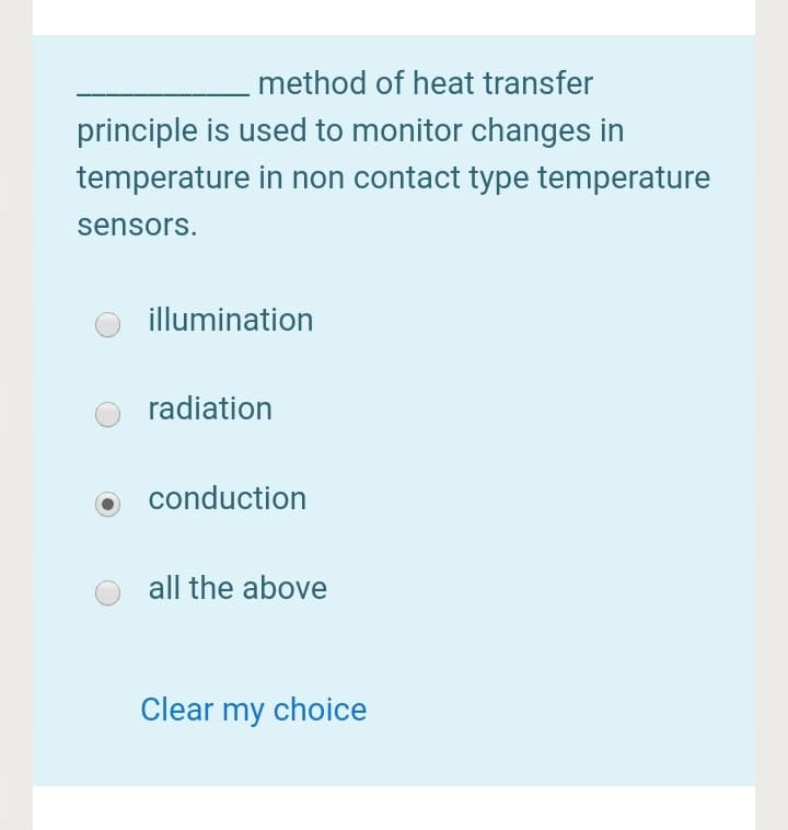
Transcribed Image Text:method of heat transfer
principle is used to monitor changes in
temperature in non contact type temperature
sensors.
illumination
radiation
conduction
all the above
Clear my choice
Expert Solution
This question has been solved!
Explore an expertly crafted, step-by-step solution for a thorough understanding of key concepts.

Step by step
Solved in 2 steps

Knowledge Booster


Learn more about
Need a deep-dive on the concept behind this application? Look no further. Learn more about this topic, electrical-engineering and related others by exploring similar questions and additional content below.Recommended textbooks for you
EBK ELECTRICAL WIRING RESIDENTIAL
Electrical Engineering
ISBN:
9781337516549
Author:
Simmons
Publisher:
CENGAGE LEARNING - CONSIGNMENT
EBK ELECTRICAL WIRING RESIDENTIAL
Electrical Engineering
ISBN:
9781337516549
Author:
Simmons
Publisher:
CENGAGE LEARNING - CONSIGNMENT