mpany. Determine the -y and secondary win- ted with a load with ar e apparent power abso
mpany. Determine the -y and secondary win- ted with a load with ar e apparent power abso

Power System Analysis and Design (MindTap Course List)
6th Edition
ISBN:9781305632134
Author:J. Duncan Glover, Thomas Overbye, Mulukutla S. Sarma
Publisher:J. Duncan Glover, Thomas Overbye, Mulukutla S. Sarma
Chapter3: Power Transformers
Section: Chapter Questions
Problem 3.51P: The ratings of a three-phase three-winding transformer are Primary(1): Y connected 66kV,15MVA...

Related questions
Question
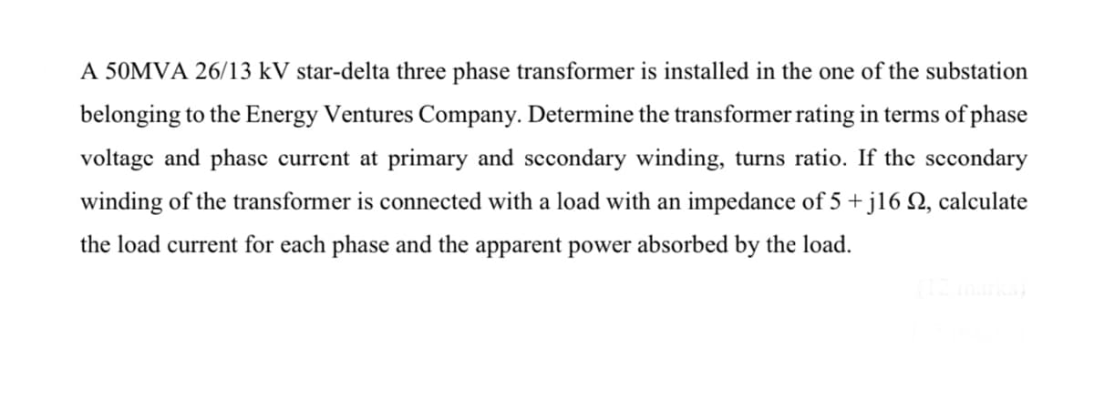
Transcribed Image Text:A 50MVA 26/13 kV star-delta three phase transformer is installed in the one of the substation
belonging to the Energy Ventures Company. Determine the transformer rating in terms of phase
voltage and phasc current at primary and sccondary winding, turns ratio. If the sccondary
winding of the transformer is connected with a load with an impedance of 5 + j16 N, calculate
the load current for each phase and the apparent power absorbed by the load.
(12marks
Expert Solution
This question has been solved!
Explore an expertly crafted, step-by-step solution for a thorough understanding of key concepts.

Step by step
Solved in 2 steps

Knowledge Booster


Learn more about
Need a deep-dive on the concept behind this application? Look no further. Learn more about this topic, electrical-engineering and related others by exploring similar questions and additional content below.Recommended textbooks for you
Power System Analysis and Design (MindTap Course …
Electrical Engineering
ISBN:
9781305632134
Author:
J. Duncan Glover, Thomas Overbye, Mulukutla S. Sarma
Publisher:
Cengage Learning

Electricity for Refrigeration, Heating, and Air C…
Mechanical Engineering
ISBN:
9781337399128
Author:
Russell E. Smith
Publisher:
Cengage Learning
Power System Analysis and Design (MindTap Course …
Electrical Engineering
ISBN:
9781305632134
Author:
J. Duncan Glover, Thomas Overbye, Mulukutla S. Sarma
Publisher:
Cengage Learning
Electricity for Refrigeration, Heating, and Air C…
Mechanical Engineering
ISBN:
9781337399128
Author:
Russell E. Smith
Publisher:
Cengage Learning